
SLIDE 1
________________________________
1 Peter Airey, Managing Director, Airey Taylor Pty Ltd; Chairman,Advanced Substructures. Email: mail@atconsulting.com.au
PRESENTATION ON INVESTIGATION OF PIPELINE FAILURE
Peter Airey1
ABSTRACT: Investigation of the causes of failure of a large diameter, high density polyethylene (HDPE) pressure pipeline. The conduit is a 25km long, 650 to 800mm diameter HDPE buried irrigation pipeline, installed parallel to the Gasgoyne River in WA. The pipeline failed during testing in December 2016. Investigations included inspection of the failed pipe length and determination of the cause of rupture of the 32mm thick pipe wall. Failure included ballooning (yielding of the pipe wall) with resulting rupture. The factors that were investigated included stress capability of HDPE material, earth loading, temperature, excessive internal static pressure, air entrapment, hydraulic surge and duration of test pressures. Following the investigation, the remediation included replacement of the failed pipe length and improved testing procedures, including having the pipe refilled, and pressure tested at 450 KPa. KEY WORDS: High density polyethylene pipeline, air valves, test pressure, safety factor, filling process.
- 1. INTRODUCTION
In 2016, a 25 km long, large diameter buried high density polyethylene (HDPE) pipeline was installed parallel to the Gascoyne River near Carnarvon WA. During final filling operations on Dec 19, 2016 (prior to a scheduled pressure test) a section of 800 mm diameter pipe failed (burst). The following discussion outlines the investigation into the cause of the failure. The pipeline is a transmission main for collecting and conveying groundwater from a bore field to irrigation properties adjacent to the Gascoyne River.
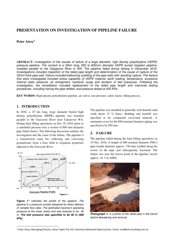
Figure 1” indicates the profile of the pipeline. The pipeline is a pressure conduit designed for direct delivery
- f variable flow rates. The estimated maximum operating
pressure at the lower (west) end was forecast to be 40
- m. The test pressure was specified to be 60 m (600
kPa).
The pipeline was installed in generally well drained sand (with about 15 % fines). Bedding and backfill was specified to be compacted excavated material. A minimum cover for the 800 nominal diameter piping was specified to be 850 mm.
- 2. FAILURE
The pipeline failed during the final filling operations on 19 Dec, 2016. A length of 800 nominal diameter PN6.3 pipe (inside diameter approx. 736 mm) yielded along the crown of the pipe and subsequently fractured. The failure was near the lowest point of the pipeline (invert
- approx. 16 .5 m AHD).