
SLIDE 1
Presentation marine application Fuel Free Power Magnetic Generator - - PDF document
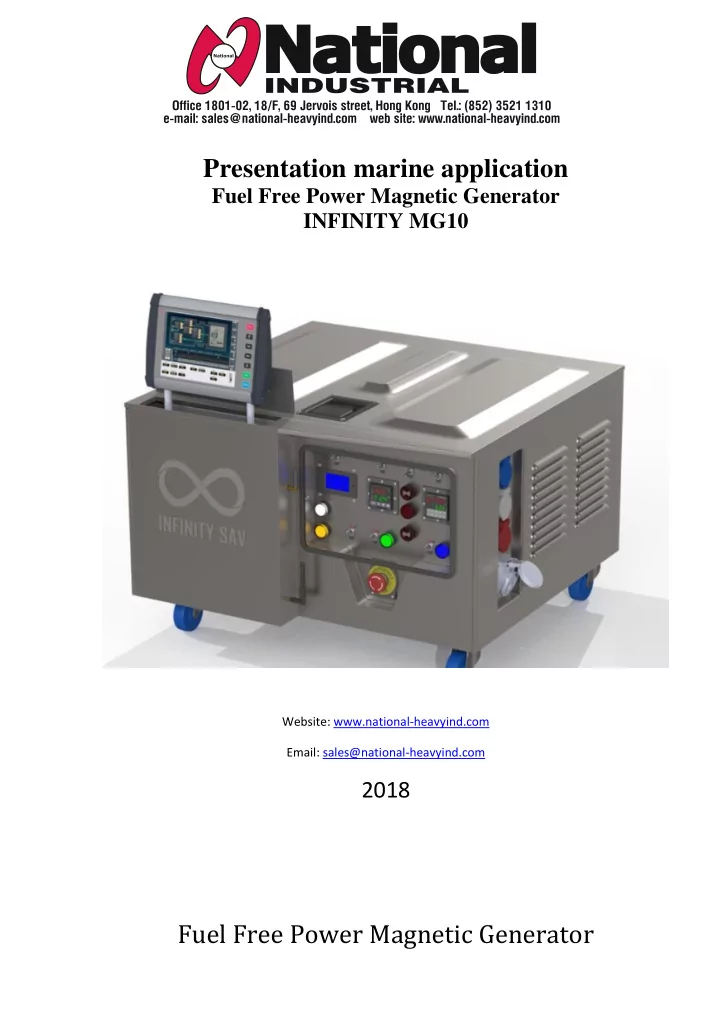
Presentation marine application Fuel Free Power Magnetic Generator INFINITY MG10 Website: www.national-heavyind.com Email: sales@national-heavyind.com 2018 Fuel Free Power Magnetic Generator INFINITY MG 10 Engine Room Engine, generator
Engine, generator and gearbox – ship’s propulsion system
Primary Diesel Generator Ship’s infrastructure energy supply BackUp Electromagnetic Generator – Infinity MG 10