
SLIDE 1
E.1
EE 109 Unit E - Pulse Width Modulation
E.2
Power
- Recall (or learn) that Power is a measure of:
– Energy per unit time
- In an electronic circuit, P = I * V
– Power = Current & Voltage (each may be varying w/ time)
- A circuit that draws a constant 2 mA of current at a constant 5V would
consume 10 mW
- Since voltage and current may change rapidly, it is often helpful to
calculate the average power
- Just sum the total power and divide by the total time
5V 0V
1 s .5s 1 s .3s
I = 1A Average Power = (1*5*.8)/2 = 2W
E.3
Output Devices
- What do the following have in common?
– Servo motor that can rotate to any angle w/in 180 degrees – Light dimmer – Oven or microwave with various power levels
- They are controlled by Pulse Width Modulation (PWM)
– Usually a 3-pin interface: Power (Vcc), GND, PWM Signal
E.4
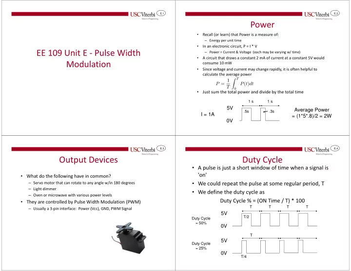
Duty Cycle
- A pulse is just a short window of time when a signal is
'on'
- We could repeat the pulse at some regular period, T
- We define the duty cycle as
Duty Cycle % = (ON Time / T) * 100
5V 0V
T T/2
5V 0V
T T/4 T T T Duty Cycle = 50% Duty Cycle = 25%