Massachusetts Eye and Ear Infirmary Harvard Medical School
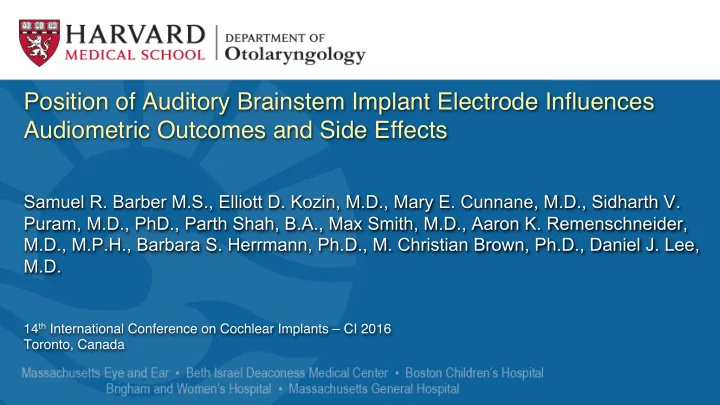
Position of Auditory Brainstem Implant Electrode Influences - - PowerPoint PPT Presentation
Position of Auditory Brainstem Implant Electrode Influences Audiometric Outcomes and Side Effects Samuel R. Barber M.S., Elliott D. Kozin, M.D., Mary E. Cunnane, M.D., Sidharth V. Puram, M.D., PhD., Parth Shah, B.A., Max Smith,
Massachusetts Eye and Ear Infirmary Harvard Medical School
No disclosures or conflicts of interest
Massachusetts Eye and Ear Infirmary Harvard Medical School
- ABI’s are placed directly over the brainstem
in proximity to the dorsal cochlear nucleus (DCN)
- Placement is “blind” and electrophysiology is
utilized to confirm placement
- Audiometric outcomes vary widely among
similar cohorts
- Electrodes are commonly inactivated due to
side effects
1
Background
Auditory Brainstem Implant placement
Massachusetts Eye and Ear Infirmary Harvard Medical School
MPR View: Electrode positioning is impossible to determine
- Standard Axial View:
windmill streak artifact present
- 1
Rationale
Artifact obscures electrode position in post-op CT
Nucleus Profile ABI 541 with flexible array (Cochlear) (NOT FDA APPROVED)
Massachusetts Eye and Ear Infirmary Harvard Medical School
We hypothesize that: 1) Post-operative Computed Tomography (CT) can resolve electrode array position in 3D space. 2) CT determined ABI array positions correlate with audiometric data and side effects.
1
Hypothesis
ABI electrode array position can be resolved
Massachusetts Eye and Ear Infirmary Harvard Medical School
- 4 Pediatric (non-NF2) and 7 Adult ABI subjects (6 NF2, 1 non-NF2) from our institution
- (IRB approved protocols #340312, #441528, #444277). POSTER 101 SESSION B
- True axial series were reformatted in Multiplanar Reconstruction (MPR) using the
McRae line. DICOM files were imported into Osirix MD v.7.0.1 64-bit. Basion and electrode tip coordinates were marked in MPR
- CT series were then viewed in 3D Maximum Intensity Projection (MIP)
2
Methods
Methods 3D Reconstruction of Post-operative CT
Basion Proximal Electrode Tip
Massachusetts Eye and Ear Infirmary Harvard Medical School
360o view of post-operative axial CT scan
2
Methods
3D Maximum Intensity Projection
Massachusetts Eye and Ear Infirmary Harvard Medical School
- 3D maximum intensity projection (MIP) revealed electrode array position
- Linear and angular measurements between marked coordinates were made
using standard posterior and lateral views
2
Methods
3D Reconstruction of Post-operative CT
Massachusetts Eye and Ear Infirmary Harvard Medical School
2
Methods
A new classification system for electrode positions
Massachusetts Eye and Ear Infirmary Harvard Medical School
Post-activation data included:
- The number and distribution of
active electrodes and side effects
- Psychophysical threshold (T)
levels during perceptual testing
2
Methods
Audiometric Analysis
Massachusetts Eye and Ear Infirmary Harvard Medical School
3
Results
A wide variety of angles were observed
- All arrays were
normalized to the right side for comparison
- the majority of electrodes
have a range of angles between 0-90 degrees with respect to the horizontal.
Massachusetts Eye and Ear Infirmary Harvard Medical School
3
Results
Subject Responses: T Values, disabled electrodes (X)
Subject T Values Subject T Values
4 Pediatric Subjects (2 revisions) 6 Adult Subjects (All displayed as if R side)
Posterior view
Massachusetts Eye and Ear Infirmary Harvard Medical School
3
Results
Some orientations may be more optimal than others
Combined Classification n (Adult, Pediatric) Mean number of active electrodes (n) Mean number of side effects (n) Mean T’s during ABI programming (n) Type IA (1, 1) 12 (2) 2.5 (2) 98.4 CL (2) Type IB (0, 1) 14 (1) 3 (1) 135.29 CL (1) Type IIA (0, 3) 14 (3) 0 (3) 99.62 CL (2) Type IIB* (1, 1) 11.5 (2) 6 (1) 142.36 CL (1) Type IIIA (1, 0) 8 (1) 5 (1) 92 CL (1) Type IV Type D (1, 0) (2, 0) 12 (1) 12 (2) 7 (1) 10.5 (2) 125.5 CL (1) 165.79 CL (2)
Combined Classification Types in Subjects with Audiometric Data
T = Threshold value for ABI programming map * 2 additional adult subjects with IIB did not have audiometric data
Massachusetts Eye and Ear Infirmary Harvard Medical School
4
Discussion / Conclusion
The potential for more optimum placement
Left Side Right Side
- This study is the first to analyze post-
- perative ABI array orientation and
correlate with audiometric data.
- A classification system was devised that
characterizes electrode array position in the skull.
- ABI placement varies widely among
patients and may explain the range of
- utcomes seen among similar cohorts.
- The use of imaging may potentially
- ptimize array placement, improve
auditory outcomes, and reduce side effects.
Massachusetts Eye and Ear Infirmary Harvard Medical School
4
Discussion / Conclusion
ABI electrode array position can be resolved
- Limitations of our study include:
- Inability to resolve neural structures
with CT
- Reliance on behavioral responses from
young children and NF2 with comorbidities
- Small sample size
- Prospective studies on larger numbers of
patients will determine the predictive value
- f ABI location on hearing outcomes and
side effects.
Massachusetts Eye and Ear Infirmary Harvard Medical School
Clinical ABI team and Acknowledgements
- Daniel J. Lee, MD
- Fred Barker, II ,MD
- Barbara Herrmann, PhD
- Christine Carter, Sc.D
- M. Christian Brown, PhD
- Aaron K. Remenschneider, MD, MPH
- Sidharth V. Puram, MD, PhD
- Elliott D. Kozin, MD
- Mary E. Cunnane, MD
- Parth Shah, BA
Massachusetts Eye and Ear Infirmary Harvard Medical School
3
Results
A wide variety of linear distances were observed
Basion
- Linear distances were difficult to
normalize due to variable anatomy between subjects
- A few adult and pediatric
subjects had values beyond twice the standard error of the mean (dotted line)
- This subgroup was analyzed to