Balacchi HF Rules and electrode design in practice Rules and - - PDF document

balacchi hf
SMART_READER_LITE
LIVE PREVIEW

Balacchi HF Rules and electrode design in practice Rules and - - PDF document

Balacchi HF Rules and electrode design in practice Rules and electrode design in practice The welding rules are made of brass strip and are available in a wide range of profiles to enable a variety of welds to be performed. Potential customer can


slide-1
SLIDE 1

1

Balacchi HF

Rules and electrode design in practice Rules and electrode design in practice

The welding rules are made of brass strip and are available in a wide range of profiles to enable a variety

  • f welds to be performed.

Potential customer can find here the profound explanation for what purposes the rules profiles are made

  • for. Also, this manual would serve to distinguish between the normal welding to the 'borderless'

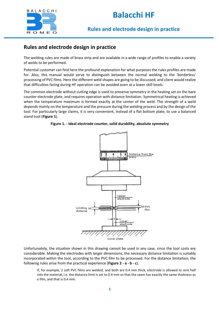
processing of PVC films. Here the different weld shapes are going to be discussed, and client would realize that difficulties facing during HF operation can be avoided even at a lower skill levels. The common electrode without cutting edge is used to preserve symmetry in the heating set on the bare counter electrode plate, and requires operation with distance limitation. Symmetrical heating is achieved when the temperature maximum is formed exactly at the center of the weld. The strength of a weld depends mainly on the temperature and the pressure during the welding process and by the design of the

  • tool. For particularly large claims, it is very convenient, instead of a flat bottom plate, to use a balanced

stand tool (Figure 1). Figure 1. - Ideal electrode counter, solid durability, absolute symmetry Unfortunately, the situation shown in this drawing cannot be used in any case, since the tool costs are

  • considerable. Making the electrodes with larger dimensions, the necessary distance limitation is suitably

incorporated within the tool, according to the PVC film to be processed. For the distance limitation, the following rules arise from the practical experience (Figure 2 - a - b - c).

If, for example, 2 soft PVC films are welded, and both are 0.4 mm thick, electrode is allowed to sink half into the material, i.e. the distance limit is set to 0.4 mm so that the seam has exactly the same thickness as a film, and that is 0.4 mm.

slide-2
SLIDE 2

2

Balacchi HF

Rules and electrode design in practice

In practice, even thicker films are welded, they measure 1 mm or more, and for them following applies:

up to 1 mm, overall thickness that is electrode allowed to sink into is half, or about 0.5 mm. If, for example, the package thickness is about 1.5 mm, the electrode distance from bottom plate should be at about 1 mm, less will weaken the weld. Stronger the material, the greater is the weld bead. Moreover, where the total thickness is 2 mm, the sinking of the electrode distance limit is set to 1.5 mm.

Figure 2. Distance limitation Same rule applies also for determining the cutting edge height (Figure 3). A cutting edge - also called separating edge or knife edge – is used for a distance limitation of weld; therefore it limits the depth of penetration and the machine setting. In a series of experiments, the above information about separating edges has proven to be correct. The height difference between the knife edge and bridge electrode is already dimensioned according to the construction of the processed plastic-film thickness. But separating edges require insulation that already exists in the majority of cases of hard paper. This material prevents short circuits. It has, unfortunately, certain disadvantages: hard paper forms a heat accumulation stage, because it has a very high dielectric loss factor, and thus transforms radiofrequency energy to heat. This results in an asymmetrical temperature distribution in the weld.

slide-3
SLIDE 3

3

Balacchi HF

Rules and electrode design in practice

How wide the bar or the electrode should be? As input information, the film thickness can be used as calculating factor which determines penetration depth or distance limit and cutting edge height. According to these values, is can be also determined the width of the electrode. When using electrodes with cutting edge, you will no longer need to adjust the distance limit on the machine. Figure 3. Electrodes with cutting edge The cutting edge height depends on the thickness film to be processed. Refer to Figure 2. a-b-c Here is a formula that gives the good practical guidelines: B = 2 x d is used.

The ridge or electrode width “B” is calculated by the total film thickness “d” multiplied by 2. If, for example, several layers of film with the thickness of 1 mm are used, just select the ridge width of 2 mm. When thin materials are used, such as, for example, in the rainwear industry, the procedure is the same; 2 films of 0.12 mm give total thickness of 0.24 mm. These multiplied by 2 gives 0.48 mm. According to this, the electrode needs to be only 0.48 mm wide, so we can round it to 0.5 mm. This dimension is sufficient for welding completely the two thin films.

You should not choose with thin films relatively wide seam, because it does not give better seam strength, you just consume too much HF energy. Still, with weak material do not use special electrodes; this has primarily to do with the appearance and not with the strength of the weld something: you do not want to achieve any visual effect. It should be mentioned here, that the construction of relatively small electrode ridges is quite difficult. You should, therefore, use stronger, settled material.

slide-4
SLIDE 4

4

Balacchi HF

Rules and electrode design in practice

Decorative seams and seam strength You need to know, without any doubt, that each welding brings with itself a weakening of the material, and thus a reduction in strength. For leather goods - films with different embossing - very often a decorative stitching is used to make good appearance. The stitching can be made of different types, mainly used to lockstitch-like designs. Welded seams, which undergo tensile stress, in particular in case

  • f thin films (for example, for curtains and rain coats) undergo an excessive stress on the weld. At these

locations, often a tearing can occur along the weld. Moreover, under normal conditions of processing with hard paper backing, the strength ratios are changed asymmetrically in the individual films. (Figures 4 - a, b). The lateral of tearing can be reduced by using decorative seams, if not avoided altogether. If the stitching is designed so that a discontinuous weld has no interruptions, the film structure between the various welding points is maintained. In that way, great strength is ensured. If the product made of thin material needs to have greater durability, a welding aid can be used, consisting

  • f open mesh textile or gauze.

Figure 4-a Figure 4-b This is placed between the slides in the welds. Such tools are already supplied in tape form. For better weld ability, these tapes are provided with PVC or other welding aids. This fabric inserts required for welding need a broader interpretation of the electrodes, since the individual fabric threads must be anchored well with the films during processing. The textile threads do not seize up in the true sense with the PVC material but are only superficially embedded (mechanically anchored).

slide-5
SLIDE 5

5

Balacchi HF

Rules and electrode design in practice

These fabric inserts can be also put everywhere where advanced strength is needed, when object is under stronger movement stresses. Book covers, sheet protectors (for menus) and similar products can thus be significantly improved in terms of breaking strength of the claimed seams. (Figure 5) Figure 5 – fabric insert Overlapped seam For this purpose choose the ridge width different than the initially mentioned, with regard to the greater seam strength. In the overlapped seam, it is not just about the seam strength, but also about the appearance (Figure 6) Figure 6 - The overlapped seam

slide-6
SLIDE 6

6

Balacchi HF

Rules and electrode design in practice

After welding, the strength that is obtained is uniform. If the starting material has a certain surface grain, it will give the welding electrode a suitable embossing, so the appearance of the surface does not appear extremely disturbed. If, for example, a book cover is made from different colored films, the overlapped portions will be weld. This gives the required uniformity in the support surface. The blank surface must be worked precisely for the overlap. The two films are placed on the steel plate, third of the electrode width one above the other, wherein the distance boundary is set to a film thickness. Sketch # 6 explains this. In order to achieve a clean appearance of the seam, the high frequency power should be carefully adjusted. The amount of the energy can be seen for each case on the instrument of the generator. After welding, the two homogeneous interconnected foils are smooth and can, as already mentioned, be subjected to further

  • processing. To get not do too much coarse material, you should choose the best grooved electrode rod,

suitable for graining decoration. Shock-edge uniform welding or butt welding By using plastic films, it can be achieved beautiful mosaic-like effects; figures from contrast colored foils can be weld togethe (figure 7). As a result of the penetration, a little foil is always displaced. This means that an additional film itself - usually made of transparent material – must be used for putting under the two precisely tailored cover sheets. The parts that need to be welded must be exactly about one on another without the slightest gap, without overlapping in the least. The punching is done with highest possible accuracy by using steel blade. The thus obtained "figure" then fits perfectly into the differently colored section. Blanks that exist in template will be formed under the electrode in such way that the two abutting edges of the films are exactly in the middle. The ridge width is chosen best from 1.5 to 3 mm, depending on the character size and material thickness. Punches are done to the the back, so that films can be placed during the punching process on face, and then we can proceed according to the method just described, and we can achieve a very nice welding effect, which has a startling seam at the correct setting of the HF energy and the electrode. Figure 7 - Butt welding a) b)

slide-7
SLIDE 7

7

Balacchi HF

Rules and electrode design in practice

Laceration as drawbacks They often occur in finished articles - either immediately after welding or after a few days - so-called

  • lacerations. This refers to the popping of the films on the cutting edge side. Accordingly, it occurs only

when using electrodes with cutting edges. This error must be strictly avoided. It is important to ensure that the cutting edge of the electrode is not too sharp. The distance between the cutting edge and welding bar must not be too large. If not doing so, errors are manifested by the formation of bulges. Sketch 8 explains the process. Besides material properties, for this error is essentially responsible the high welding pressure on the cutting edges. From the start, from placing of material, tool is responsible for punching and cutting. During the welding process, consequently, the pre-cut film is swelled and broken off from the weld. Figure 8 – Lacerations The rimless welding has gain a lot of interest. For years, many plastic processors had tried to depart from the normal types of welding. Especially with photo albums, ring binders or car visor, wherever an ever so small seam is cumbersome or undesirable. For example, book covers condemning particularly large margins seams, tilt already at normal room temperature when setting up the book. Experts call it "flat feet on the book cover." This disadvantage is well known. The rimless weld bypasses inappropriate processing. One of the most straightforward methods is characterized by simple electrode design. We only use cutting edges; the facet is directed by the welding rod. The electrode rests on a sliding table. The cardboard inserts

slide-8
SLIDE 8

8

Balacchi HF

Rules and electrode design in practice

are pre-cut, as precisely as possible, and are placed at a small distance to the electrode. (Film thickness times 2 gives the distance between the electrode and cardboard.) You can easily push the board into the electrode; the lining film comes over and pushes the electrode under the press. Of course, you should not go with too much pressure in such welds so that the cover sheet is not incised in the cold state. The finished products can be easily cut. They will have sharp edges. Borderless welding In these almost borderless welds, the seam is heated always one-sided. As we know, you have to work at cutting edge with hard paper as a base. Thus, the symmetry of the weld rod is transferred to the hard paper side. The strength of the seam is low: They can, with a shearing motion tear (figure 9a). Figure 9 - borderless welds The electrode rod is milled like a roof, it has two edges. The actual cutting edge is higher than the other part, to ca. 0.15 mm. This welding bar includes a counter electrode which is made of brass, and serves as a support or counter-

  • template. But because this type requires absolute symmetry in the weld, shall under no circumstances be

used with hard paper, for heat barrage to work. Therefore, the distance limit, which is taken into account already in the design tool, must be set exactly. For lining up counter electrodes, the centering is done by use of nuts, bolt. (Figure 10).

slide-9
SLIDE 9

9

Balacchi HF

Rules and electrode design in practice

Electrodes of this type do not require a lot of pressure, and if pull-down devices are installed, this must be taken into account when setting up the pressure. In the high -frequency field, the material is heated within the roof-shaped milled electrode and softens up to its yield value. The heated plastic logically has the tendency to evade the upcoming pressure. Thus, the main part of the material between the cutting edge and sub-electrode is forced to pass to form a wedge-shaped bead between the two films. The remaining material is escaping towards the other side. This way, the films not

  • nly heat excessively, but are also symmetrically mechanically coupled, thanks to the lower electrode,

during the welding process. That way, large strength of the weld is achieved. Even with a strong tearing movement, it is not possible to separate the two sheets. To achieve this good strength in the borderless welding, it must be considered the type of tool. The energy absorption is somewhat greater than with the use of "only cutting edge". It should be consider that on both sides of the electrode greater heat dissipation is done due to the absence of the hard paper support (Figure 11). Figure 10 -Tool design for rimless welding

slide-10
SLIDE 10

10

Balacchi HF

Rules and electrode design in practice

Figure 11 - Welding conditions The electrode width will be at normal film thickness 2-2.5 mm, while increasing the rod width with stronger material to 3-3.5 mm. For thicker films, there is also the difference in height between the edges. From experience, this goes up to 0.3 mm. The sensitivity of such tools is comparable with the usual electrodes, but the finished product will look better and durability will be much better. It gives perfect

  • seam. Whoever takes these facts in account, will have smooth production.