
SLIDE 1
1
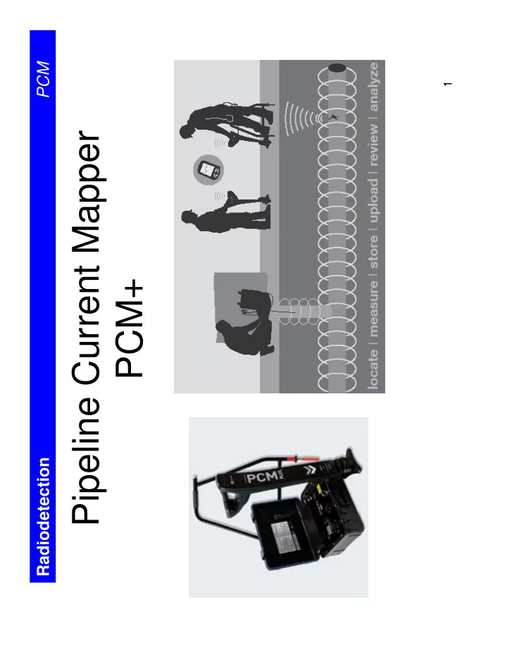
Pipeline Current Mapper PCM+
Radiodetection PCM
Pipeline Current Mapper PCM+ Radiodetection Radiodetection PCM - - PDF document
PCM 1 Pipeline Current Mapper PCM+ Radiodetection Radiodetection PCM The PCM can. Find contacts with other structures Evaluate Pipe Coating for defects Perform periodic Pipeline surveys Find defective Insulation joints
1
Radiodetection PCM
2
Radiodetection PCM
3
Radiodetection PCM
4
Radiodetection PCM
test point AC Tx signal strength (dBmA) distance
DC 4Hz 1KHz
5
Radiodetection PCM
fault
6
Radiodetection PCM
7
Radiodetection PCM
8
Radiodetection PCM
9
Radiodetection PCM
10
Radiodetection PCM
11
Radiodetection PCM
12
Radiodetection PCM
13
Radiodetection PCM
100 % 95 %
14
Radiodetection PCM
15
Radiodetection PCM
1 2 3 4 5 6 7 8 9 10 LOCATION Nr 1 1 1 1 AMPS
LINEAR COMPARISONS
Data obtained during comparative tests on site
16
Radiodetection PCM
Transmitter short target line
17
Radiodetection PCM
18
Radiodetection PCM
19
Radiodetection PCM
Transmitter
A-Frame
20
Radiodetection PCM
21
Radiodetection PCM
22
Radiodetection PCM
23
Radiodetection PCM
24
Radiodetection PCM
25
Radiodetection PCM
26
Actual PCM Results
– typically better then 6"
why the left side of graph climbs quickly.
under..