
SLIDE 1
- R. J. Wilkes
- Email: phy115a@u.washington.edu
Physics 115
General Physics II Session 35
AC circuits Reactances Phase relationships Evaluation
06/05/14 1 1
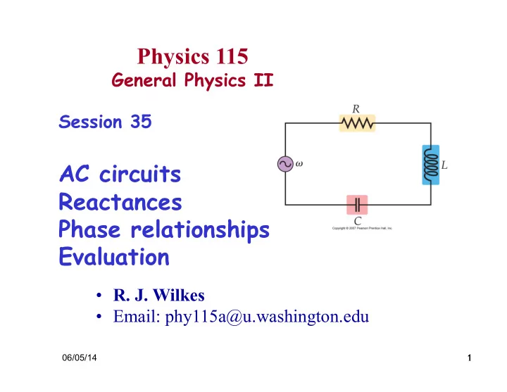
Physics 115 General Physics II Session 35 AC circuits Reactances - - PowerPoint PPT Presentation
Physics 115 General Physics II Session 35 AC circuits Reactances Phase relationships Evaluation R. J. Wilkes Email: phy115a@u.washington.edu 06/05/14 1 1 Lecture Schedule Today 6/5/14 2 Announcements Please pick up class
06/05/14 1 1
6/5/14 2
3 3 6/5/14
6/5/14 4
5
2 =VR 2 +(VL −VC)2 = R2 +(X L − X C)2
6/5/14
6 6/5/14 6
( ω = radians/s, f=cycles/s )
7 6/5/14
Fixed length, rotating Length of y component = V(t) or I(t) V and I are aligned
7
http://www.kwantlen.ca/science/physics/ faculty/mcoombes/P2421_Notes/ Phasors/sine.gif
8 6/5/14 8
9 6/5/14
2 ¡]
9
10 6/5/14 10
11 6/5/14
2 ¡]
11
12 6/5/14 12
13 6/5/14
RMS R