
SLIDE 1
Department of Chemical Engineering I.I.T. Bombay, India
In general, the lead block of the transfer function speeds up the - - PowerPoint PPT Presentation
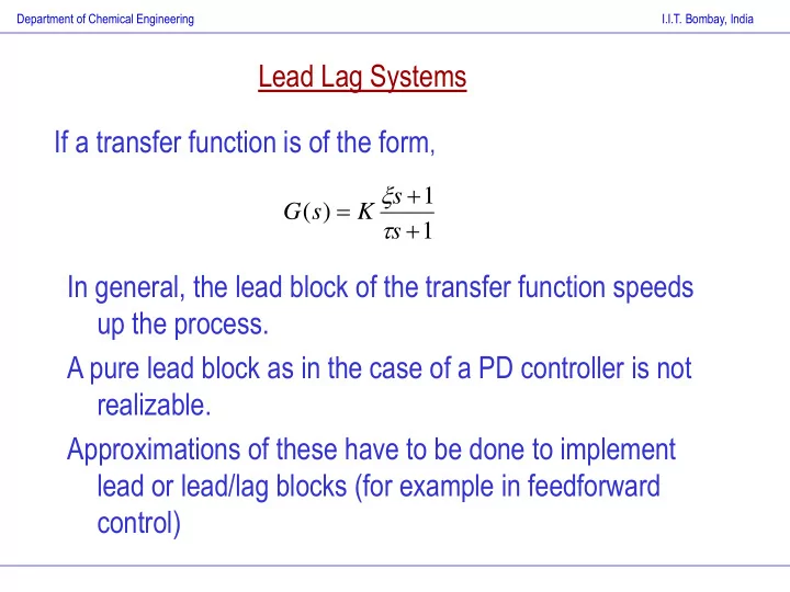
Department of Chemical Engineering I.I.T. Bombay, India Lead Lag Systems If a transfer function is of the form , s 1 G ( s ) K s 1 In general, the lead block of the transfer function speeds up the process. A
Department of Chemical Engineering I.I.T. Bombay, India
Department of Chemical Engineering I.I.T. Bombay, India
1
Department of Chemical Engineering I.I.T. Bombay, India
Department of Chemical Engineering I.I.T. Bombay, India
Department of Chemical Engineering I.I.T. Bombay, India
h1
h2
Second order systems can arise because of two first order systems in interacting or noninteracting setups Inherent dynamics in the system is of higher order U-tube manometer. Presence of a controller in a closed loop even if the process is first order (such as PI or PID controllers in a closed loop) can give a second order system.
Department of Chemical Engineering I.I.T. Bombay, India
h1 h2
2 2 2 1 1 2 2 2 1 1 1 1
Department of Chemical Engineering I.I.T. Bombay, India
1 2 2 1 2 2 1 2 1 2 2 1 2 1 1 2 2 2 1 1 1
Department of Chemical Engineering I.I.T. Bombay, India
t d I d c
t d I d c
d I c c
2 2 1
Plant controller yd +
u
Department of Chemical Engineering I.I.T. Bombay, India
2 2 2