
SLIDE 1
Physics 115
General Physics II Session 29
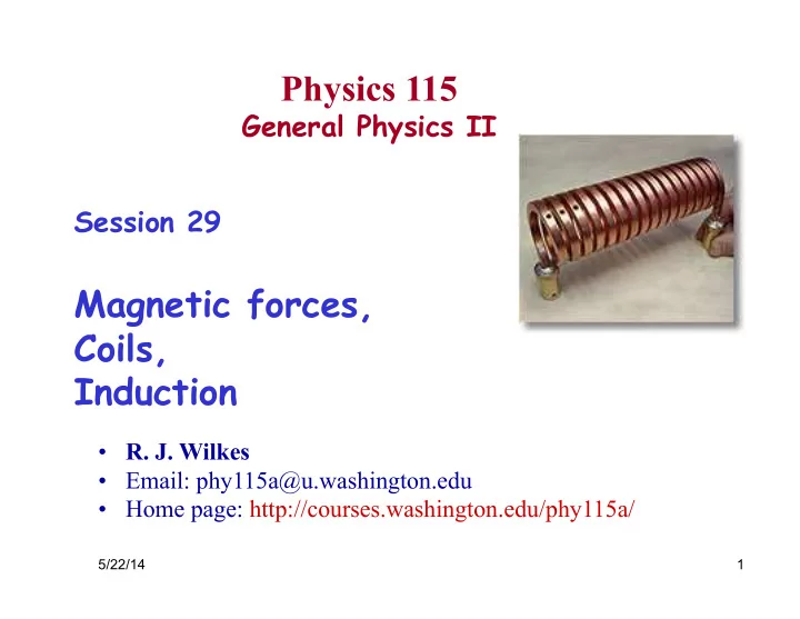
Magnetic forces, Coils, Induction
5/22/14 1
- R. J. Wilkes
- Email: phy115a@u.washington.edu
- Home page: http://courses.washington.edu/phy115a/