
SLIDE 1
+
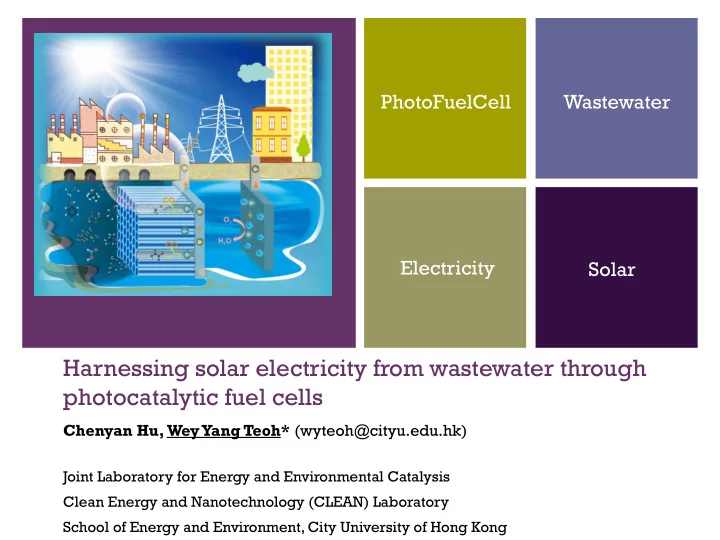
Harnessing solar electricity from wastewater through photocatalytic fuel cells
Chenyan Hu, Wey Yang Teoh* (wyteoh@cityu.edu.hk)
Joint Laboratory for Energy and Environmental Catalysis Clean Energy and Nanotechnology (CLEAN) Laboratory School of Energy and Environment, City University of Hong Kong