
SLIDE 1
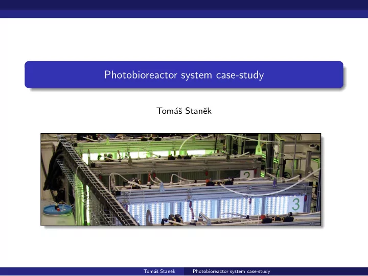
Photobioreactor system case-study
Tom´ aˇ s Stanˇ ek
Tom´ aˇ s Stanˇ ek Photobioreactor system case-study
Photobioreactor system case-study Tom a s Stan ek Tom a s Stan - - PowerPoint PPT Presentation
Photobioreactor system case-study Tom a s Stan ek Tom a s Stan ek Photobioreactor system case-study Tom a s Stan ek Photobioreactor system case-study Overal description Various devices with some autonomous logic and
Tom´ aˇ s Stanˇ ek Photobioreactor system case-study
Tom´ aˇ s Stanˇ ek Photobioreactor system case-study
Tom´ aˇ s Stanˇ ek Photobioreactor system case-study
Tom´ aˇ s Stanˇ ek Photobioreactor system case-study
Tom´ aˇ s Stanˇ ek Photobioreactor system case-study
Tom´ aˇ s Stanˇ ek Photobioreactor system case-study
Tom´ aˇ s Stanˇ ek Photobioreactor system case-study
Tom´ aˇ s Stanˇ ek Photobioreactor system case-study
Tom´ aˇ s Stanˇ ek Photobioreactor system case-study
Tom´ aˇ s Stanˇ ek Photobioreactor system case-study
Tom´ aˇ s Stanˇ ek Photobioreactor system case-study
Tom´ aˇ s Stanˇ ek Photobioreactor system case-study
Tom´ aˇ s Stanˇ ek Photobioreactor system case-study
Tom´ aˇ s Stanˇ ek Photobioreactor system case-study
Tom´ aˇ s Stanˇ ek Photobioreactor system case-study
Tom´ aˇ s Stanˇ ek Photobioreactor system case-study
Tom´ aˇ s Stanˇ ek Photobioreactor system case-study
Tom´ aˇ s Stanˇ ek Photobioreactor system case-study
Tom´ aˇ s Stanˇ ek Photobioreactor system case-study
Tom´ aˇ s Stanˇ ek Photobioreactor system case-study
Tom´ aˇ s Stanˇ ek Photobioreactor system case-study
Tom´ aˇ s Stanˇ ek Photobioreactor system case-study
Tom´ aˇ s Stanˇ ek Photobioreactor system case-study
Tom´ aˇ s Stanˇ ek Photobioreactor system case-study
Tom´ aˇ s Stanˇ ek Photobioreactor system case-study
Tom´ aˇ s Stanˇ ek Photobioreactor system case-study
Tom´ aˇ s Stanˇ ek Photobioreactor system case-study
Tom´ aˇ s Stanˇ ek Photobioreactor system case-study
Tom´ aˇ s Stanˇ ek Photobioreactor system case-study
Tom´ aˇ s Stanˇ ek Photobioreactor system case-study
Tom´ aˇ s Stanˇ ek Photobioreactor system case-study
Tom´ aˇ s Stanˇ ek Photobioreactor system case-study
Tom´ aˇ s Stanˇ ek Photobioreactor system case-study
Tom´ aˇ s Stanˇ ek Photobioreactor system case-study
Tom´ aˇ s Stanˇ ek Photobioreactor system case-study
Tom´ aˇ s Stanˇ ek Photobioreactor system case-study
Tom´ aˇ s Stanˇ ek Photobioreactor system case-study
Tom´ aˇ s Stanˇ ek Photobioreactor system case-study
Tom´ aˇ s Stanˇ ek Photobioreactor system case-study
Tom´ aˇ s Stanˇ ek Photobioreactor system case-study
(define (agent ch stop-rv pumping-model) (let loop ((pump-off-rv never-rv) (measure-rv (always-rv #t))) (rv-select (rv-wrap (recv-rv ch) (match-lambda ((’set-pump! on/off) (model-put! pumping-model on/off) (send ch ‘(ok)) (loop (if on/off (timeout-rv 5) never-rv) msr-rv)) (else (send ‘(error "invalid command")) (loop pump-off-rv msr-rv)))) (rv-wrap pump-off-rv (lambda ( ) (print "pump timeout: turning off the pump") (model-put! pumping-model #f) (loop never-rv msr-rv))) (rv-wrap measure-rv (lambda ( ) (print "some periodic measurement") (loop pump-off-rv (timeout-rv 2)))) (rv-wrap stop-rv (lambda ( ) (print "shutdown")))))) Tom´ aˇ s Stanˇ ek Photobioreactor system case-study
Tom´ aˇ s Stanˇ ek Photobioreactor system case-study
Tom´ aˇ s Stanˇ ek Photobioreactor system case-study
Tom´ aˇ s Stanˇ ek Photobioreactor system case-study
Tom´ aˇ s Stanˇ ek Photobioreactor system case-study
Tom´ aˇ s Stanˇ ek Photobioreactor system case-study
Tom´ aˇ s Stanˇ ek Photobioreactor system case-study
Tom´ aˇ s Stanˇ ek Photobioreactor system case-study