P a r k P o t o m a c O f f i c e B u i l d i n g E Kyle Wagner l - - PowerPoint PPT Presentation

p a r k p o t o m a c o f f i c e b u i l d i n g e
SMART_READER_LITE
LIVE PREVIEW

P a r k P o t o m a c O f f i c e B u i l d i n g E Kyle Wagner l - - PowerPoint PPT Presentation

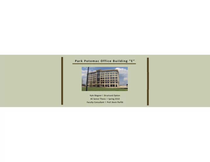
P a r k P o t o m a c O f f i c e B u i l d i n g E Kyle Wagner l Structural Option AE Senior Thesis l Spring 2010 Faculty Consultant l Prof. Kevin Parfitt Presentation Overview Project Information Existing Structural System g y


slide-1
SLIDE 1

P a r k P o t o m a c O f f i c e B u i l d i n g “ E ”

Kyle Wagner l Structural Option AE Senior Thesis l Spring 2010 Faculty Consultant l Prof. Kevin Parfitt

slide-2
SLIDE 2

Presentation Overview

  • Project Information
  • Existing Structural System

g y

  • Problem Statement and Solution
  • Structural Depth Study
  • Cost and Schedule Analysis
  • Additional Topics
  • Conclusions
  • Acknowledgements
  • Questions and Comments
slide-3
SLIDE 3

Project Information

Presentation Overview

  • Project Information
  • Existing Structural System
  • Located off I‐270 in Potomac, MD
  • Problem Statement and Solution
  • Structural Depth Study
  • Cost and Schedule Analysis
  • Additional Topics
  • Part of Park Potomac Place
  • Focal point from Cadbury Ave.
  • Prominent location within Community
  • Townhomes, Office Space, Retail, Dining

p

  • Conclusions
  • Acknowledgements
  • Questions and Comments

www.parkpotomacplace.com

  • Face of community from I‐270

View from Cadbury Ave

slide-4
SLIDE 4

Project Information

  • Two levels mostly underground parking
  • 100 000+ SF each

Presentation Overview

  • Project Information
  • Existing Structural System
  • 100,000+ SF each
  • Approx. 25,000 SF each
  • Seven levels of mostly office space
  • Problem Statement and Solution
  • Structural Depth Study
  • Cost and Schedule Analysis
  • Additional Topics

North Entrance to Parking Levels Building Footprint

p

  • Conclusions
  • Acknowledgements
  • Questions and Comments
slide-5
SLIDE 5

Existing Structural System

  • Underground Parking all Cast‐in‐place concrete

7” Thi k l b t t i d i N S di ti

Presentation Overview

  • Project Information
  • Existing Structural System
  • 7” Thick slab post‐tensioned in N‐S direction
  • Concrete Moment Frames

in both directions

  • 72” x 20” D Beams post‐tensioned in E‐W direction

L S li h d

  • Problem Statement and Solution
  • Structural Depth Study
  • Cost and Schedule Analysis
  • Additional Topics

Existing Structural System

  • Long Spans accomplished
  • Flexibility for Tenant
  • 12’ Cantilever at N, S ends

p

  • Conclusions
  • Acknowledgements
  • Questions and Comments
slide-6
SLIDE 6

Problem Statement

  • Concrete structure results in large building self weight

Presentation Overview

  • Project Information
  • Existing Structural System
  • Larger gravity members result
  • Large mat foundations at soil level
  • Central Foundation 52’ x 64’ x 60” Deep
  • Longer schedule duration from concrete construction
  • Problem Statement and Solution
  • Structural Depth Study
  • Cost and Schedule Analysis
  • Additional Topics

Existing Foundation Plan

  • End Result: Negative Cost and Schedule Implications

p

  • Conclusions
  • Acknowledgements
  • Questions and Comments
slide-7
SLIDE 7

Problem Solution

  • Reduce building self weight by utilizing a steel structure

Presentation Overview

  • Project Information
  • Existing Structural System
  • Maintain current column layout
  • Maintain current ceiling heights in Tenant Spaces
  • Maintain current MEP Spaces
  • To maintain integrity of existing design:
  • Composite Beams and lightweight concrete used
  • Problem Statement and Solution
  • Structural Depth Study
  • Cost and Schedule Analysis
  • Additional Topics
  • Maintain current MEP Spaces
  • Braced Frames used to resist lateral forces
  • Steel construction likely to reduce construction schedule
  • Parking levels will remain unchanged

p

  • Conclusions
  • Acknowledgements
  • Questions and Comments
slide-8
SLIDE 8

Project Goals

  • Reduce building self weight

Presentation Overview

  • Project Information
  • Existing Structural System
  • Reduce schedule duration
  • Reduce overall cost
  • Maintain integrity of tenant spaces
  • Problem Statement and Solution
  • Structural Depth Study
  • Cost and Schedule Analysis
  • Additional Topics

p

  • Conclusions
  • Acknowledgements
  • Questions and Comments
slide-9
SLIDE 9

Design Loads

  • Design Loads

Floor Live Loads Area Design Load (psf) ASCE 7‐05 Load (psf) Assembly Areas 100 100 Corridors 100 100

Presentation Overview

  • Project Information
  • Existing Structural System
  • ASCE 7‐05

Corridors Above First Floor 80 80 Lobbies 100 100 Marquees & Canopies 75 75 Mechanical Rooms 150 125 Offices 80 + 20 psf Partitions 50 + 20 psf Partitions Parking Garages 50 40 Plaza, Top Floor Parking Fire Truck Load or 250 psf 250 Retail‐ First Floor 100 100 Stairs and Exitways 100 100 Storage (Light) 125 125

  • Superimposed Dead Loads
  • 5 psf Floor
  • 10 psf Roof
  • Problem Statement and Solution
  • Structural Depth Study
  • Cost and Schedule Analysis
  • Additional Topics

Storage (Light) 125 125

  • Flat Roof Snow Load
  • 21 psf

Live Load Values

p

  • Conclusions
  • Acknowledgements
  • Questions and Comments
slide-10
SLIDE 10

G r a v i t y S y s t e m D e s i g n

  • 5 ½” Thick Slab on 2”, 18 Gage Metal Decking

P id d t 2 h fi ti b t fl

Presentation Overview

  • Project Information
  • Existing Structural System
  • Provides adequate 2 hour fire rating between floors
  • Unshored
  • Beams spacing does not exceed 10’
  • Minimize number
  • f beams required
  • Problem Statement and Solution
  • Structural Depth Study
  • Cost and Schedule Analysis
  • Additional Topics
  • Columns spliced every
  • ther floor
  • f beams required

RAM Model Typical Floor Layout

p

  • Conclusions
  • Acknowledgements
  • Questions and Comments
slide-11
SLIDE 11

Cantilevered Ends

  • 12’ Cantilever on North and South Ends
  • Unobstructed glass around building
  • Moment connection at

interior to balance moment at column

Presentation Overview

  • Project Information
  • Existing Structural System
  • Four beams used to transfer
  • Unobstructed glass around building

corners

  • Moment from cantilever: 575 ft‐k
  • Moment from interior: 376 ft‐k
  • Moment to column: 199 ft‐k
  • Problem Statement and Solution
  • Structural Depth Study
  • Cost and Schedule Analysis
  • Additional Topics

load back to columns

  • Beam required:
  • W18x55
  • Final Design shown at right
  • Design for moment and axial due to

gravity load

p

  • Conclusions
  • Acknowledgements
  • Questions and Comments
slide-12
SLIDE 12

Floor Depth Comparison

  • Existing post‐tensioned system
  • 20” depth at beams
  • Maintain ceiling heights and MEP Spaces

Presentation Overview

  • Project Information
  • Existing Structural System
  • 20 depth at beams
  • Steel Design
  • Deepest Beam: W27x84
  • Increase overall building height
  • No code restrictions
  • Problem Statement and Solution
  • Structural Depth Study
  • Cost and Schedule Analysis
  • Additional Topics
  • Floor Depth Approx. 32”
  • Increase by 12” per floor
  • Overall height increase by 7’
  • Recalculate lateral loads

p

  • Conclusions
  • Acknowledgements
  • Questions and Comments
slide-13
SLIDE 13

Lateral Loads

  • Wind: Method 2 of ASCE 7‐05 Chapter 6

Presentation Overview

  • Project Information
  • Existing Structural System
  • Seismic: ELFP of ASCE 7‐05 Chapter 11
  • Seismic Design Category B
  • Seismic Base Level taken at plaza level
  • Assume wind negligible beneath plaza level

Wi d t ll d f t th d i bilit

  • Problem Statement and Solution
  • Structural Depth Study
  • Cost and Schedule Analysis
  • Additional Topics
  • Wind controlled for strength and serviceability

p

  • Conclusions
  • Acknowledgements
  • Questions and Comments
slide-14
SLIDE 14

ETABS Model

  • 7 Load combinations, 4 wind cases, accidental

Presentation Overview

  • Project Information
  • Existing Structural System

torsion (5% ecc.) due to seismic all manually included

  • Floors modeled as rigid diaphragms
  • Loads distributed based on relative stiffnesses of frames
  • Only lateral system modeled

G i l d li d i ddi i l di h

  • Problem Statement and Solution
  • Structural Depth Study
  • Cost and Schedule Analysis
  • Additional Topics

ETABS Model

  • Gravity loads applied using additional area mass to diaphragm

p

  • Conclusions
  • Acknowledgements
  • Questions and Comments
slide-15
SLIDE 15

Braced Frame Design

  • Symmetry in Geometry and Stiffness

Presentation Overview

  • Project Information
  • Existing Structural System
  • SAP used to calculate forces in braces

for critical load combination

  • Loads distributed evenly to each frame
  • Problem Statement and Solution
  • Structural Depth Study
  • Cost and Schedule Analysis
  • Additional Topics

N-S Braced Frame

for critical load combination

E-W Braced Frame

  • Critical load combination used to design columns
  • Final Brace Frame Design shown at right
  • E‐W Frames larger than N‐S Frames

p

  • Conclusions
  • Acknowledgements
  • Questions and Comments
slide-16
SLIDE 16

Lateral Analysis

  • Primary controlling load case was 0.9D+1.6W

Presentation Overview

  • Project Information
  • Existing Structural System
  • Overall building torsion was negliglible
  • Wind drift within L/400
  • Center of mass and rigidity both at geometric center
  • Controlling wind case was Wind Case 1
  • Seismic drift found to be well within limitations
  • Problem Statement and Solution
  • Structural Depth Study
  • Cost and Schedule Analysis
  • Additional Topics
  • Seismic drift found to be well within limitations

p

  • Conclusions
  • Acknowledgements
  • Questions and Comments
slide-17
SLIDE 17

Foundation Design

Presentation Overview

  • Project Information
  • Existing Structural System
  • Problem Statement and Solution
  • Structural Depth Study
  • Cost and Schedule Analysis
  • Additional Topics
  • Existing foundations
  • Steel Structure Foundations
  • 17’ x 17’ x 34” Deep (U.N.O.)

p

  • Conclusions
  • Acknowledgements
  • Questions and Comments
slide-18
SLIDE 18

Cost/ Schedule

  • Detailed takeoffs completed for both systems

Original Structure Mat'l Labor Equipment Total COST/SF Foundations $272,327 $59,403 $250 $331,980 $1.90 Superstructure $2,532,939 $1,594,087 $48,370 $4,175,396 $23.86 Total Incl. Additional Costs $27.83

Presentation Overview

  • Project Information
  • Existing Structural System
  • Total Structure cost reduced by 25%
  • Foundations cost reduced 78%

Steel Redesign Mat'l Labor Equipment Total COST/SF Foundations $54,082 $17,076 $1,874 $73,033 $0.42 Superstructure $2,669,627 $290,079 $114,563 $3,074,269 $17.57 Total Incl. Additional Costs $19.43

  • Problem Statement and Solution
  • Structural Depth Study
  • Cost and Schedule Analysis
  • Additional Topics
  • Assuming $50 per SF of building enclosure
  • $224,000 additional
  • Final Steel cost of $20.69 per SF
  • Schedule predicted to be decreased by approx. 10 months
  • General conditions savings not factored into cost results

p

  • Conclusions
  • Acknowledgements
  • Questions and Comments
slide-19
SLIDE 19

Additional Topics

  • Architectural Study

Presentation Overview

  • Project Information
  • Existing Structural System
  • Design of Connections
  • Problem Statement and Solution
  • Structural Depth Study
  • Cost and Schedule Analysis
  • Additional Topics

p

  • Conclusions
  • Acknowledgements
  • Questions and Comments
slide-20
SLIDE 20

Further Improvements

Presentation Overview

  • Project Information
  • Existing Structural System
  • Potential to reduce floor depth
  • Potential to balance additional moment
  • Problem Statement and Solution
  • Structural Depth Study
  • Cost and Schedule Analysis
  • Additional Topics
  • From Earlier:
  • Deepest Beam: W27x84
  • Use W21 x 93 instead
  • Unbalanced moment: 199 ft‐k
  • Conclusions
  • Acknowledgements
  • Questions and Comments
  • Constrain 10 beams on each floor
  • Floor depth required: 32” 26”
  • Overall height increase by 3.5’, not 7’
  • Decreasing cantilever distance or increase

moment on interior

  • Much smaller columns will result
slide-21
SLIDE 21

Conclusions

Presentation Overview

  • Project Information
  • Existing Structural System
  • Reduce building self weight
  • Problem Statement and Solution
  • Structural Depth Study
  • Cost and Schedule Analysis
  • Additional Topics
  • Reduce schedule duration
  • Reduce overall cost
  • Maintain integrity of tenant spaces
  • Conclusions
  • Acknowledgements
  • Questions and Comments
  • Steel could have been a viable and beneficial alternative.

Office Building “E”

slide-22
SLIDE 22

A c k n o w l e d g e m e n t s

A special thanks to:

Presentation Overview

  • Project Information
  • Existing Structural System
  • Frank Malits
  • Daniel Camp
  • Problem Statement and Solution
  • Structural Depth Study
  • Cost and Schedule Analysis
  • Additional Topics
  • Karl Alt

PSU Architectural Engineering Faculty

  • Conclusions
  • Acknowledgements
  • Questions and Comments
slide-23
SLIDE 23

Q u e s t i o n s / C o m m e n t s

Presentation Overview

  • Project Information
  • Existing Structural System
  • Problem Statement and Solution
  • Structural Depth Study
  • Cost and Schedule Analysis
  • Additional Topics
  • Conclusions
  • Acknowledgements
  • Questions and Comments