SLIDE 2 Why doesn't it always work?
- Cast shadows (foreground object can change background)
- Interreflections (green screen can reflect, so foreground takes
- n color of background)
- Foreground object might happen to have same color as
background (in Step 3) -- see green screen example 2 slides ago
- Soft edges become hard (mask) e.g Hair and furry object
boundaries are difficult to model with a binary mask. Now let's look at a more general situation....
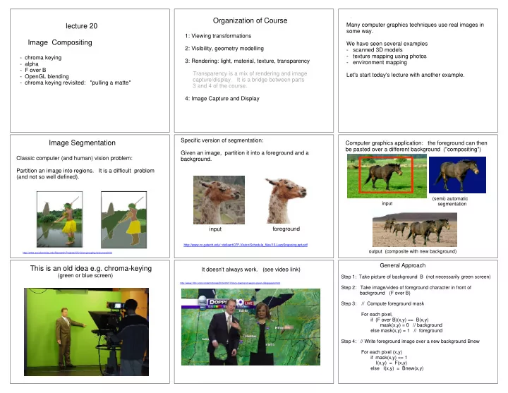
lecture 20 Image Compositing
- chroma keying
- alpha
- F over B
- OpenGL blending
- Chroma keying revisited: "pulling a matte"
Partially occupied pixels & "alpha"
Think of a pixel as a little square. The occupancy or coverage of a pixel is called "alpha". 0 means not occupied at all (transparent). 1 means fully occupied (opaque) 0 < < 1 means partially occupied In representing RGB images is common to include a 4th component to indicate how much of the pixel is occupied, so we have RGBA. Typically one uses 8 bits for each "channel" so this gives 32 bits per pixel.
Examples of RGBA
(0, 0, 0, 1) - black and opaque (1, 0, 0, 1) - red and opaque etc. (1, 1, 1, 1) - white and opaque In the following, I used "premultiplied" notation (explained soon) (.5, 0, 0, .5) - red and 50% transparent (.5, .5, .5, .5) - white and 50% transparent (.1, .1, .1, .5) - dark grey and 50% transparent (.1, .1, .1, .1) - white and 10% opaque (90% transparent) (0, 0, 0, 0) - color undefined, 100% transparent
I will sometimes write RGB and sometimes rgb. The reasons will be explained later ("premultiplied values") To give you a flavour of what's to come.... Q: How do we darken a pixel without changing its opacity ? A: darken( Irgb
r, g, b, I
Q: How do we change the opacity
changing the underlying color (sometimes called "dissolve") ? dissolve( Irgb
r, g, b,
Where do alpha values come from ?
In OpenGL, we can define surfaces as partially transparent. e.g. diffuse_material = [ 1, 0, 0, 0.5 ] glMaterial(GL_FRONT, GL_DIFFUSE, diffuse_material) drawPolygon() The material has a red color with 50% transparency.
// glEnable(GL_BLEND) // glBlendFunc (GL_SRC_ALPHA, GL_ONE_MINUS_SRC_ALPHA) // explain later // glDisable(GL_DEPTH_TEST) def drawYellowTriangle(): glBegin (GL_TRIANGLES) glColor4f(1.0, 1.0, 0.0, 0.75) # yellow glVertex3f(0.1, 0.9, 0.0) glVertex3f(0.1, 0.1, 0.0) glVertex3f(0.7, 0.5, 0.0) glEnd() def drawCyanTriangle(): # cyan glBegin (GL_TRIANGLES) glColor4f(0.0, 1.0, 1.0, 0.75) glVertex3f(0.9, 0.9, 0.0) glVertex3f(0.3, 0.5, 0.0) glVertex3f(0.9, 0.1, 0.0) glEnd() def drawMain(): glPushMatrix() drawYellowTriangle() // right pair drawCyanTriangle() glTranslatef(-1,0, 0) drawCyanTriangle() drawYellowTriangle() // left pair glPopMatrix()
https://www.opengl.org/archives/resources/code/samples/redbook/alpha.c http://stackoverflow.com/questions/16774372/opengl-alpha-blending-and-object-independent-transparency
If you draw blue first, then green will be drawn over blue at each pixel. However, there are some pixels in which the green rectangle is behind the blue one. (Drawing the green first creates a similar problem.) The solution is similar to the painter's algorithm: split one of the rectangles and draw them from far to near. In the previous example, all triangles were in the z=0 plane (and depth buffering was turned off). I just wanted to illustrate that the drawing
Here is another example which illustrates a more subtle point. For this example, there is no correct order to draw the two rectangles, since you cannot say that one rectangle is over another.
lecture 20 Image Compositing
- chroma keying
- alpha
- F over B
- OpenGL blending
- Chroma keying revisited: "pulling a matte"