Optimizing LHCD in Improved L-mode t target plasmas t l A. - - PowerPoint PPT Presentation

optimizing lhcd in improved l mode t target plasmas t l
SMART_READER_LITE
LIVE PREVIEW

Optimizing LHCD in Improved L-mode t target plasmas t l A. - - PowerPoint PPT Presentation

Optimizing LHCD in Improved L-mode t target plasmas t l A. Hubbard, E. Marmar, B. Lipschultz, J.W. Hughes, D. Whyte, G. Wallace, R. Parker J W Hughes D Whyte G Wallace R Parker Ideas Forum Jan 2011 Motivation: Improved L-mode


slide-1
SLIDE 1

Optimizing LHCD in Improved L-mode t t l target plasmas

  • A. Hubbard, E. Marmar, B. Lipschultz,

J W Hughes D Whyte G Wallace R Parker

Motivation:

J.W. Hughes, D. Whyte, G. Wallace, R. Parker Ideas Forum Jan 2011

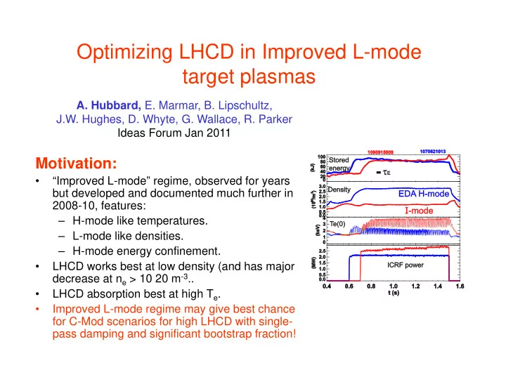
  • “Improved L-mode” regime, observed for years

but developed and documented much further in 2008-10, features: H mode like temperatures – H-mode like temperatures. – L-mode like densities. – H-mode energy confinement.

  • LHCD works best at low density (and has major

LHCD works best at low density (and has major decrease at ne > 10 20 m-3..

  • LHCD absorption best at high Te.
  • Improved L-mode regime may give best chance

f C M d i f hi h LHCD ith i l for C-Mod scenarios for high LHCD with single- pass damping and significant bootstrap fraction!

slide-2
SLIDE 2

In 2010, coupled LHCD into 900 kA I-mode encouraging but needs development encouraging but needs development

  • At density of nebar 1.3-1.4 x 10 20

3 ( 30%

b li it i L m-3 (~30% above ne limit in L- modes), we did see increased non-

  • thermals. But, still lower than is

consistent with efficient current consistent with efficient current drive. Di ti t ti i

  • Directions to optimize:

– Decrease I-mode density (likely by decreasing current. Unfortunately this also decreases P and T ) this also decreases PL-I, and Tped.) – Increase LH power (was 600 kW). – Decrease inner wall gap (increases HXR in L-modes.) HXR in L modes.)

slide-3
SLIDE 3

Experimental Proposal

  • Scope out low density range for I-modes, vs current (at 0.9, 0.8, 0.7 MA).

Try lower Ip, which so far have not given good I-modes. Knobs to try:

– Recent boronization (Mo radiation has been a problem at low density). Neon seeding which may reduce Mo – Neon seeding, which may reduce Mo. – Use cryopump. – Increase ICRF power to max before H-mode transitions.

  • Once steady “Improved L-mode” target is established, for lowest density

at each Ip, add LHCD at maximum available power. Monitor:

– J(r) changes via MSE, polarimetry, Vloop, sawtooth behaviour…. ( ) g , p y,

loop,

– Non-thermals via Hard X-rays, ECE – SOL profiles (probes, reflectometer).

Detailed analysis and simulation using TSC ACCOME and

  • Detailed analysis and simulation using TSC, ACCOME and

GENRAY/CQL3D to assess bootstrap and driven current, compare to

  • expt. Use these to optimize future advanced scenarios, make

predictions for capabilities using higher LH power when available.