OMAE 2008-57047 Offshore Drilling Riser VIV Suppression Devices - - PowerPoint PPT Presentation

omae 2008 57047 offshore drilling riser viv suppression
SMART_READER_LITE
LIVE PREVIEW

OMAE 2008-57047 Offshore Drilling Riser VIV Suppression Devices - - PowerPoint PPT Presentation

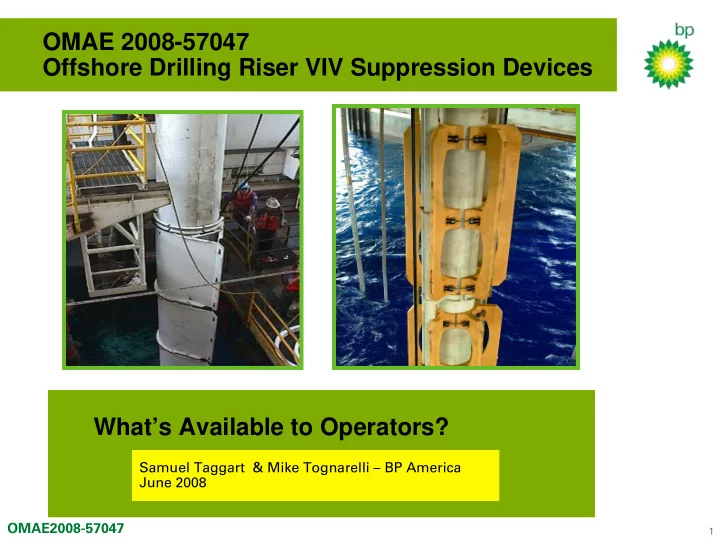
OMAE 2008-57047 Offshore Drilling Riser VIV Suppression Devices Whats Available to Operators? Samuel Taggart & Mike Tognarelli BP America June 2008 OMAE2008-57047 1 Deepwater Drilling in Loop Currents Operational Issues :


slide-1
SLIDE 1

1

OMAE2008-57047

OMAE 2008-57047 Offshore Drilling Riser VIV Suppression Devices What’s Available to Operators?

Samuel Taggart & Mike Tognarelli – BP America June 2008

slide-2
SLIDE 2

2

OMAE2008-57047

Deepwater Drilling in Loop Currents

Operational Issues :

  • Types of drill rig – DP and Moored

– manoeuvrability

  • In combination with hurricane

season – retrieval ability

  • Production drilling over subsea

architecture – consequential damage

  • Unproductive drilling time – 2005

many tens of millions of dollars

slide-3
SLIDE 3

3

OMAE2008-57047

Improving Drilling Operations in High Currents

A company equipment review produced two main areas of interest : 1. Riser devices that decrease drag and suppress VIV 2. Development of improved mechanical drilling riser centraliser

  • Increases the operational window for retrieval of riser
  • Particularly important during hurricane season
  • To be deployed for operation in 2008

This paper will address the work done in the area of available devices for drag reduction and suppression of VIV

slide-4
SLIDE 4

4

OMAE2008-57047

FLOW DEVICES – Summary History

Types of flow improving devices: Passive Devices

  • fairings, shrouds, etc.

Active Devices

  • Air, water jetting,etc

Drilling Riser hard up against diverter housing in a 2 knot current

The BENEFITS

  • Reduce drag - Riser top and bottom angle
  • Suppress VIV – Riser vibrations
slide-5
SLIDE 5

5

OMAE2008-57047

Some Passive Devices

Passive Devices

  • Fairings (rigid)
  • Deformable Shrouds
  • Buoyancy Modules
  • Distribution
  • Helical Grooved
  • Axial Rod Shrouds
  • Perforated Shrouds
  • Windings / helical wraps
  • Hoops / Spaced Spoilers
  • Fins / Bumper Bars
  • Splitter plates
  • Bumps / Waves

AIMS Splitter Full fairing

slide-6
SLIDE 6

6

OMAE2008-57047

Passive Devices, cont’d

Inverted Helically Grooved buoyancy Wavy Buoyancy profile Axial Rod Shrouds Perforated Cylindrical Shroud Lankhorst Fins on Drilling Riser Helical Rope Wrap Hoops / Spaced Spoilers

slide-7
SLIDE 7

7

OMAE2008-57047

Operational Device Review - Findings

Nearer Term most favourable options for operation 1. Fairings (rigid) – various designs and associated performance claims 2. Fairings (flexible) – prototype construction underway 3. Fins / Bumper bars – designs in use 4. Helical Wraps – previously used as temporary mitigation All but one in use today on GoM Drill Rigs Benefit Decision for Deployment

  • a. Performance – dynamic behaviour benefit ?
  • b. Robustness – survivability
  • c. Marine logistics – container transfer , storage and available work areas
  • d. Deployment/Recovery efficiency – time management GoM Hurricane impact
  • e. Mechanical Handling – Crew resources, cross lifting, rig modifications
  • f. Health/Safety/Environment – dropped objects, failure risks and consequence

Need to perform an Operational Benefit Analysis – Numeric (Time / Cost)

slide-8
SLIDE 8

8

OMAE2008-57047

Fairings – Need for Performance Acceptance

To help understand and clarify Fairing Performance against Claims 1. Establish a performance acceptance criteria for fairing products (i.e. see paper for specifics)

  • Drag Reduction level set
  • VIV Suppression , Stability and Motion Amplitude

2. Invite suppliers to put forward products for large scale BP proving tests Two fairing suppliers came forward with products

  • AIMS Inc. – Dual Fin Splitter Fairing
  • Trelleborg Offshore – RiserFin Fairing

3. A 3rd company Allbrown also requested proof of concept tests on their flexible fairing -

slide-9
SLIDE 9

9

OMAE2008-57047

Fairings – Acceptance Model Tests

  • Performed at Institute for Ocean Technology in St. John’s – Free Vibration on Springs
  • Specific deepwater drilling riser (OD=1.33m) scaled to 0.24 for tests
  • Model test matrix targeted for full scale ranges of Re and Vrn

Model Cylinder

0.00 5.00 10.00 15.00 20.00 25.00 1.00E+04 1.00E+05 1.00E+06 1.00E+07 Reynolds Number Reduced velocity 0.25 Hz 0.50 Hz 0.75Hz 1.00Hz 1.50Hz 2.00Hz 3.00Hz `

  • Comprehensive fixed and freely vibrating tests performed
  • Bare pipe benchmarking tests
  • 2 Off fairing type acceptance test sets
slide-10
SLIDE 10

10

OMAE2008-57047

AIMS Dual Fin Splitter - ADFS

AIMS Splitters Installed and Prepped for Testing (88% Coverage Including Dummy Section) Fairing Section Thrust collar Endplate

slide-11
SLIDE 11

11

OMAE2008-57047

Trelleborg RiserFin Fairing

Fairing Section Thrust collar Endplate

slide-12
SLIDE 12

12

OMAE2008-57047

Fairing Results + Conclusions

  • Both Fairing Products tested satisfied the ‘Acceptance Criteria’ for Drag

Reduction and VIV suppression

  • Typical drag coefficient (Cd) were around 0.6 with good VIV suppression

Drag Cofficient vs. Reynolds Number AIMS Fairing

0.1 0.2 0.3 0.4 0.5 0.6 0.7 0.8 0.9 1

200000 400000 600000 800000 1000000 1200000 1400000 1600000 1800000 Reynolds Number (Re) Drag Coefficient (CD) Fixed (rough) Free (rough) Fixed (polished)

Drag Coefficient vs. Reynolds Number CRP Fairing - Free Vibration 0.1 0.2 0.3 0.4 0.5 0.6 0.7 0.8 0.9 1

200000 400000 600000 800000 1000000 1200000 1400000 1600000 Reynolds Number (Re) Drag Coefficient (Cd) Free Test

  • Poly. (Free Test )

Amplitude ration vs. Nominal Reduced Velocity AIMS Fairing

0.00 0.02 0.04 0.06 0.08 0.10

5 10 15 20 25 30 Nominal Reduced Velocity (U*) Am plitude Ratio (A*)

slide-13
SLIDE 13

13

OMAE2008-57047

VT Fairing – Concept Proving

  • Operational target is to get over some of the

downside impact of working with rigid fairing – lighter , flexible , easy storage , less work area demand

  • Concept proving model tests completed at

University of Southampton – limited Re range tested

  • Results showed that VT highly effective at

suppressing VIV with reduced dynamic drag loading

slide-14
SLIDE 14

14

OMAE2008-57047

Full Scale Operational Experience

  • Model tests indicate benefit but how do fairings perform for

real ?

  • BP measuring and monitoring behaviour of deepwater drilling

risers for a number of years

  • Two drilling campaigns have been under taken with different

types of fairings (SGSI designs)

  • Indications are that the fairings did suppress VIV behaviour in

higher current situations

slide-15
SLIDE 15

15

OMAE2008-57047

GSF Explorer Drilling Riser

Fairings Data:

  • 7 buoyant joints equipped with fairings
  • Shell Global Solutions, Inc. (SGSI) -

full wrap fairings

  • Chord/Diameter (C/D) Ratio: 1.5
  • Length: 6 ft

Monitoring Data:

  • 9 months of monitoring
  • VIV occurs 1.6% of time
  • Max current below 0.5 knots except for period of 21st

July to 27th July 07 when a max current speed of 2.1 knots observed

11 Slick Joints WT =0.875" BOP LMRP Lower FJ 21 joints 3000ft rating Buoyancy 13.0 ft –––––– Seabed 39.0 ft –––––– 62.8 ft –––––– 1187.8 ft –––––– MSL 4595 ft Well head 4 Slick Joints WT =0.750" 887.8 ft –––––– 1637.8 ft –––––– Drill Floor Intermediate FJ Termination Joint & Pup Tensioner Ring Outer Barrel Inner Barrel & Pup Joint Diverter & Upper FJ 4542.8 ft –––––– 4669 ft 4620 ft –––––– 4647.8 ft –––––– 4412.8 ft –––––– 6 joints 5000ft rating Buoyancy 3887.8 ft –––––– 7 joints 3000ft rating Buoyancy with F airings Staggered section 4 jts 3000ft rating Buoyancy 5 jts Slick 3212.8 ft –––––– 36” & 28” Conductor (157.5 ft)

slide-16
SLIDE 16

16

OMAE2008-57047

Ocean Confidence Drilling Riser

Fairings Data:

  • 14 buoyant joints equipped with fairings
  • SGSI -

tailfin fairings

  • Chord/Diameter (C/D) Ratio: 1.45
  • Length: 6 ft

Monitoring Data:

  • 2 months of monitoring
  • VIV occurs 4.1% of time
  • Max current speed: 0.95 knots

35 ft Termination Joint BOP LMRP Lower FJ 10 ft –––––– Seabed 63 ft –––––– 473 ft –––––– MSL 4065 ft 5 Slick Joints 2273 ft –––––– Drill Floor Intermediate FJ Termination Joint & Pup Joints Tensioner Ring Outer Barrel Inner Barrel Diverter & Upper FJ 4033 ft –––––– 4153 ft 4112 ft –––––– 4135 ft –––––– 3998 ft –––––– 24 joints 5000ft rating Buoyancy 3173 ft –––––– Well head 98 ft –––––– 12 joints 3000ft rating Buoyancy (3 Top joints with Fairings) 11 joints 2000ft rating Buoyancy (with Fairings) 1125 ft of Fairings

slide-17
SLIDE 17

17

OMAE2008-57047

Conclusions

  • Fairing performance has been demonstrated to various levels of

rigor

  • The final choice for fairing use on a drilling riser for a particular

well location tends to be a pure Cost / Benefit Decision

  • Recommendations:

− Operability analyses using fairing performance data − Cost-benefit analysis: “saved” downtime vs. “lost” trip time and handling / storage issues − Attention to minimizing “lost” time in fairing designs