NUMERICAL SIMULATION OF SELF-STRUCTURING ANTENNAS BASED ON A GENETIC - - PDF document

numerical simulation of self structuring antennas based
SMART_READER_LITE
LIVE PREVIEW

NUMERICAL SIMULATION OF SELF-STRUCTURING ANTENNAS BASED ON A GENETIC - - PDF document

NUMERICAL SIMULATION OF SELF-STRUCTURING ANTENNAS BASED ON A GENETIC ALGORITHM OPTIMIZATION SCHEME J.E. Ross * E.J. Rothwell, C.M. Coleman L.L. Nagy John Ross & Associates ECE Dept. Delphi Automotive Systems 350 W 800 N, Suite 317


slide-1
SLIDE 1

Figure 1. Example antenna template. Figure 2. Block diagram.

NUMERICAL SIMULATION OF SELF-STRUCTURING ANTENNAS BASED ON A GENETIC ALGORITHM OPTIMIZATION SCHEME

J.E. Ross* John Ross & Associates 350 W 800 N, Suite 317 Salt Lake City, UT 84103 E.J. Rothwell, C.M. Coleman ECE Dept. Michigan State University

  • E. Lansing, MI 48824

L.L. Nagy Delphi Automotive Systems 30500 Mound Road Warren, MI 48090-9055

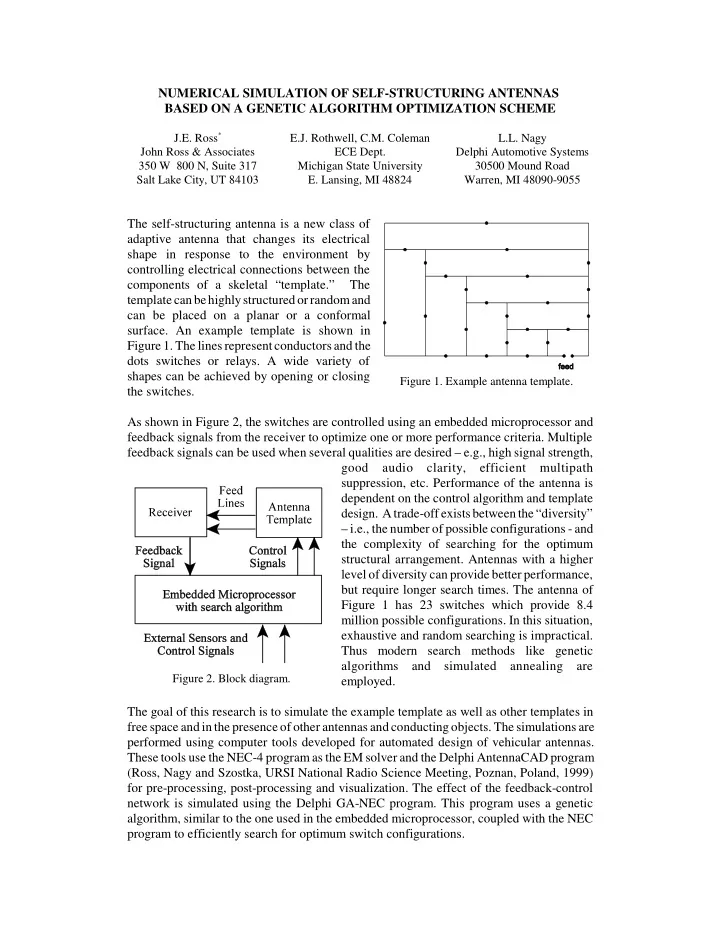
The self-structuring antenna is a new class of adaptive antenna that changes its electrical shape in response to the environment by controlling electrical connections between the components of a skeletal “template.” The template can be highly structured or random and can be placed on a planar or a conformal

  • surface. An example template is shown in

Figure 1. The lines represent conductors and the dots switches or relays. A wide variety of shapes can be achieved by opening or closing the switches. As shown in Figure 2, the switches are controlled using an embedded microprocessor and feedback signals from the receiver to optimize one or more performance criteria. Multiple feedback signals can be used when several qualities are desired – e.g., high signal strength, good audio clarity, efficient multipath suppression, etc. Performance of the antenna is dependent on the control algorithm and template

  • design. A trade-off exists between the “diversity”

– i.e., the number of possible configurations - and the complexity of searching for the optimum structural arrangement. Antennas with a higher level of diversity can provide better performance, but require longer search times. The antenna of Figure 1 has 23 switches which provide 8.4 million possible configurations. In this situation, exhaustive and random searching is impractical. Thus modern search methods like genetic algorithms and simulated annealing are employed. The goal of this research is to simulate the example template as well as other templates in free space and in the presence of other antennas and conducting objects. The simulations are performed using computer tools developed for automated design of vehicular antennas. These tools use the NEC-4 program as the EM solver and the Delphi AntennaCAD program (Ross, Nagy and Szostka, URSI National Radio Science Meeting, Poznan, Poland, 1999) for pre-processing, post-processing and visualization. The effect of the feedback-control network is simulated using the Delphi GA-NEC program. This program uses a genetic algorithm, similar to the one used in the embedded microprocessor, coupled with the NEC program to efficiently search for optimum switch configurations.

slide-2
SLIDE 2

Numerical Simulation of Self-Structuring Antennas Based on a Genetic Algorithm Optimization Scheme

by

J.E. Ross*

John Ross & Associates 350 W 800 N, Suite 317 Salt Lake City, UT 84103

E.J. Rothwell, C.M. Coleman

ECE Dept. Michigan State University East Lansing, MI 48824

L.L. Nagy

Delphi Automotive Systems 30500 Mound Road Warren, MI 48090-9055 2000 URSI National Radio Science Meeting July 17, 2000 Paper Number 23.8

slide-3
SLIDE 3

Companion Paper

Self-Structuring Antennas

by C.M. Coleman, E.J. Rothwell and J.E. Ross. Session AP-56 Novel and Active Antennas and Arrays. Wednesday 8:40 AM, Ballroom B.

slide-4
SLIDE 4

Overview

Introduction to Self-Structuring Antennas Review of Genetic Algorithms Computer Analysis Tools Numerical Results Summary

slide-5
SLIDE 5

Example antenna template. Lines represent conductors and dots represent switches or relays.

Introduction to Self-Structuring Antennas

The self-structuring antenna (SSA) is a new class of adaptive antenna that changes its electrical shape in response to the environment by controlling electrical connections between the components of a skeletal “template.”

slide-6
SLIDE 6
  • The template can be highly structured or random and

can be placed on a planar or a conformal surface.

  • A wide variety of shapes can be achieved by opening
  • r closing the switches.
  • Switches

are controlled using an embedded microprocessor and feedback signals from the receiver to optimize one or more performance criteria. Block Diagram of SSA.

slide-7
SLIDE 7
  • Multiple feedback signals can be used when several

qualities are desired – e.g., high signal strength, good audio clarity, efficient multipath suppression, etc.

  • Performance is dependent on the control algorithm and

template design.

  • A trade-off exists between the “diversity” – i.e., the

number of possible configurations - and the complexity of searching for the optimum structural arrangement.

  • Antennas with a higher level of diversity can provide

better performance, but require longer search times.

  • The prototype antenna has 23 switches which provide

8.4 million possible configurations making exhaustive and random searching impractical.

  • Modern search methods like genetic algorithms and

simulated annealing are employed for efficient searching.

  • Hardware implementation and potential applications of

SSA’s are numerous and discussed in the companion paper.

slide-8
SLIDE 8

Prototype SSA

Prototype SSA uses HP8510 Network Analyzer as a receiver with feedback provided via GPIB. A personal computer is used to control the state of 23 relays on the board. Top View of Prototype SSA.

slide-9
SLIDE 9

Review of Genetic Algorithms

GA’s are based on the principles of genetics and Darwin’s concept of natural selection. Advantages

  • Relatively efficient
  • Not as fast as gradient methods, but much faster than

random or exhaustive searches.

  • Does NOT require derivative information.
  • Tends NOT to get stuck in local minima.
  • Does NOT require initial guesses.
  • Can handle discrete or discontinuous parameters and

non-linear constraints.

  • Can find “non-intuitive” solutions.
slide-10
SLIDE 10

Chromosomes

  • Contain all information necessary to describe an

individual.

  • Composed of DNA in nature or a long binary string in

a computer model.

  • Chromosomes are composed of genes for the various

characteristics to be optimized.

  • Chromosomes can be any length depending on the

number of parameters to be optimized. Encoding

  • Defines the way genes are stored in the chromosome

and translated to actual problem parameters. A possible encoding scheme for an antenna using a 16 bit binary chromosome.

slide-11
SLIDE 11

Fitness

  • A single numerical quantity describing how well an

individual meets predefined design objectives and constraints.

  • Can be computed based on the outputs of multiple

analyses using a weighted sum.

  • Definition of good fitness functions is highly problem

dependent. Cross-Over

  • A method of exchanging genetic material between two

parents to produce offspring. Example of single point cross-over.

slide-12
SLIDE 12

THE SIMPLE GA

  • Create initial random population of individuals.

Population size depends on the problem size.

  • Evaluate the fitness of each individual according to the

predefined criteria.

  • Select individuals for mating based on fitness.
  • Fitter individuals have a higher probability of

mating and passing on their genetic information to subsequent generations.

  • Less fit individuals have a non-zero probability of

mating to preserve diversity.

  • Mating is simulated by combining the chromosomes of

two individuals at a randomly chosen crossover point.

  • Mutation is simulated by randomly changing a few bits

in the chromosome of the offspring.

  • Provides mechanism for exploring new regions of

the solution space.

  • Prevents premature convergence to local minima.
  • Evaluate fitness of new generation and repeat process

for a specified number of generations or until a desired fitness level is attained.

slide-13
SLIDE 13

Flow Diagram for Simple Genetic Algorithm

slide-14
SLIDE 14

Computer Analysis Tools

The goal of this research is to numerically investigate the characteristics of the SSA in free space and in the presence of other antennas and conducting objects.

  • Simulations are performed using computer tools

developed by Delphi Research Labs for automated design of vehicular antennas.

  • NEC-4 from Lawrence Livermore National Laboratory

is used as the EM solver.

  • AntennaCAD program is a GUI for NEC and is used

for pre-processing, post-processing and visualization.

  • Delphi’s GA-NEC program couples a genetic

algorithm (GA) to the NEC program to efficiently search for optimum antenna configurations.

slide-15
SLIDE 15

AntennaCAD

AntennaCAD is a Delphi Research Labs program that provides pre-processing, post processing and visualization tools for the NEC program.

  • Commercial CAD programs such as AutoCAD and

CADKEY are used to create and edit meshes.

  • Reads and writes wire mesh data in DXF, CADL,

IGES, GM SurfSeg and NEC formats.

  • Cued dialog boxes for NEC control commands.
  • Verifies mesh geometry prior to running NEC.
  • Provides 2-D, 3-D and wire frame plots of NEC input

and output data.

  • Graphics based on OpenGL.
slide-16
SLIDE 16

Delphi AntennaCAD display of surface current.

slide-17
SLIDE 17

GA-NEC

GA-NEC is a Delphi Research Labs program that couples a genetic algorithm with the NEC program to automatically search for optimal antenna designs.

  • GA-NEC can encode any parameter in a NEC input file

as an optimization variable.

  • Encoding methods include:
  • none
  • linear
  • decade
  • list of discrete values
  • symbolic link
  • Fitness can be configured using nearly any combination
  • f NEC output variables and user defined responses.
  • NEC output variables include:
  • Charge
  • Current
  • Impedance
  • Transmit Patterns
  • Receive Patterns
  • Near Zone Fields
  • Coupling
slide-18
SLIDE 18

GA-NEC display of GA-control, template, parameter, encoding and fitness editors.

  • Fitness goals include:
  • Minimize response.
  • Maximize response.
  • Relative match to specified response (Schwartz Inequality).
  • Absolute match to specified response.
  • Constrain less than specified response.
  • Constrain greater than specified response.
  • Constrain to be within a specified range.
  • Constrain to be outside a specified range.
slide-19
SLIDE 19

Geometry of SSA Configuration 2

Numerical Results

Due to the complexity involved in modeling control lines, the model was simplified to include only the template wires and switch elements.

slide-20
SLIDE 20

Encoding

  • Open switches were simulated by moving wire

segments a large distance away from the antenna via the NEC GM card.

  • Closed switches were simulated by simply not moving

the segments. GA Parameters

  • Simple GA with “Elitist Strategy”
  • Population Size = 100
  • Probability of Crossover = 0.6
  • Probability of Mutation = 0.01
  • Generation Gap = 95%
  • Maximum Generations = 50
slide-21
SLIDE 21

Input Impedance vs Frequency of SSA in free space.

slide-22
SLIDE 22

Input Impedance of SSA optimized for 400 MHz.

slide-23
SLIDE 23

Elevation plane pattern of SSA optimized for maximal E-Phi at 300 MHz.

slide-24
SLIDE 24

Input Impedance of SSA optimized for Zin = 200 + j0 over band from 450 to 550 MHz.

slide-25
SLIDE 25

Another result showing optimization over a band of frequencies.

slide-26
SLIDE 26

Radiation Pattern for SSA optimized for maximum E-Phi at Theta = 50 and Phi = 0 at 300 MHz.

slide-27
SLIDE 27

Current on SSA optimized for maximum E-Phi at theta=50, phi=90 and frequency = 300 MHz.

slide-28
SLIDE 28

Radiation pattern of SSA optimized for maximum E-phi at theta=50, phi = 0 and frequency =700 MHz.

slide-29
SLIDE 29

Current for SSA optimized for maximum E-Phi at theta=50, phi=0 and frequency = 700 MHz.

slide-30
SLIDE 30

Radiation pattern for SSA optimized for maximum E-Phi at Theta=50, Phi=90 and frequency = 700 MHz.

slide-31
SLIDE 31

Current on SSA optimized for maximum E-Phi at theta=50, phi=90 and frequency = 700 MHz.

slide-32
SLIDE 32

Summary

Numerical results suggest that the SSA concept may have potential for solving a variety of traditionally difficult antenna design problems.

  • Accurate analysis of the prototype SSA is hampered by

the presence of the numerous control and power supply wires.

  • Numerical simulations demonstrate that the SSA

prototype can be tuned to achieve a good match over a wide range of frequencies (approximately 150 - 800 MHz).

  • Optimizations that cover a band of frequencies show

promising results.

  • Observed that the GA generally converged faster for

higher frequencies. This is likely due to the higher diversity of the antenna at these frequencies.

  • Numerical simulations demonstrate that the SSA

should be exhibit relatively little variation in reception as the antenna is rotated relative to the source.