SLIDE 1 Normal Mode Helical Antenna
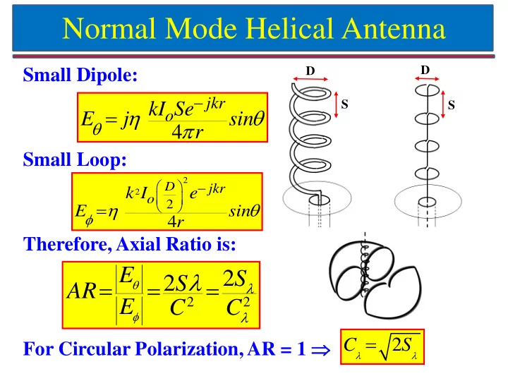
Small Dipole: Small Loop: Therefore, Axial Ratio is: For Circular Polarization, AR = 1
2 2
2 2 E S S AR E C C
4
jkr
E j sin r
2 2
2
4
D
jkr
e E sin r
2 C S
D S D S
SLIDE 2 Design of Normal Mode Helical Antenna
Radiation Resistance (Rs)
2 2
1(790) 0.6 2 Iav R h R s s Io
AR = 2 Sλ / C λ
2
= 2x0.01/0.04 2 = 12.5 = 21.94 dB
Axial Ratio (AR) For Infinite Ground Plane: Wire length ≈ λ / 4 – text book > λ / 4 – in reality Feed is tapped after one turn for impedance matching
SLIDE 3 Normal Mode Helical Antenna (NMHA)
- n Small Circular Ground Plane
SLIDE 4
NMHA Design on Small Circular Ground Plane
Resonance Frequency 1.8 GHz
Wavelength 166 mm Spacing = 0.027λ 4.5 mm Diameter of Helix = 0.033λ 5.5 mm No of Turns (N) 7 Pitch Angle (α) 14.6 Degree Length of Wire = 0.75λ 124.5 mm
SLIDE 5
Effect of Ground Plane Size on NMHA
As ground plane radius increases from λ/30 to λ/20, resonance frequency decreases and the input impedance curve shifts upward. NMHA designed for 1.8 GHz and rwire = 1.6 mm (λ/100)
SLIDE 6
Effect of Wire Radius on NMHA
As radius of wire decreases from λ/80 to λ/120, its inductance increases so resonance frequency of NMHA decreases and its input impedance curve shifts upward (inductive region). NMHA designed for 1.8 GHz and rg = 5.5 mm (λ/30)
SLIDE 7 Effect of Wire Radius on Bandwidth
SLIDE 8
Fabricated NMHA on Small Ground Plane and its Results
SLIDE 9 Horn Antennas
Electrical Engineering Department, IIT Bombay
gkumar@ee.iitb.ac.in (022) 2576 7436
SLIDE 10
Horn Antennas
H-Plane Sectoral Horn E-Plane Sectoral Horn Pyramidal Horn Conical Horn TE10 mode in Rectangular Waveguide
SLIDE 11
TE10 mode in Rectangular Waveguide
Rectangular Waveguide
b a For Fundamental TE10 mode: E-Field varies sinusoidally along ‘a’ and is uniform along ‘b’ X-Band Waveguide WR90 (8.4 to 12.4 GHz): a = 0.9” and b = 0.4” Cut-off Wavelength = 2a = 2 x 0.9 x 2.54 = 4.572 cm Cut-off Frequency = 3 x 10¹⁰ / 4.572 = 6.56 GHz
SLIDE 12
E-Plane Sectoral Horn Antenna
SLIDE 13
E-Plane Sectoral Horn: Side View
≈
SLIDE 14 E-Plane Sectoral Horn: Directivity Curve
ρ1 6 10 20 100 b1 3.46 4.47 6.32 14.14
SLIDE 15
E-Plane Sectoral Horn: Max. Phase Error
Maximum Directivity occurs when which gives ‘s’ approximately equal to:
δmax = 90°
δmax = 2πs, where
≈
Maximum Phase error occurs when y’ = b1 / 2 Phase Error too high: Not Recommended
SLIDE 16
E-Plane Sectoral: Universal Pattern
E-Field for s = 1/4 (δmax = 90°) E-Field for s = 1/8 (δmax = 45°) - Recommended
SLIDE 17
H-Plane Sectoral Horn Antenna
δmax = 2πt, where
Maximum Phase error at x’ = a1 / 2
SLIDE 18 H-Plane Sectoral Horn: Directivity Curve
ρ2 6 10 20 100 a1 4.24 5.48 7.75 17.32
a1 3λρ2
SLIDE 19
H-Plane Sectoral Horn: Max. Phase Error
Maximum Directivity occurs when which gives ‘t’ approximately equal to:
δmax = 135°
δmax = 2πt, where
Maximum Phase error occurs when x’ = a1 / 2 Phase Error too high: Not Recommended
a1 3λρ2
SLIDE 20 H-Plane Sectoral: Universal Pattern
E-Field for t = 1/4 (δmax = 90°) E-Field for t = 1/8 (δmax = 45°)
Recommended
error between 45° and 90°
SLIDE 21
Pyramidal Horn Antenna
Side View Top View
SLIDE 22
Pyramidal Horn Antenna
Condition for Physical Realization:
SLIDE 23 Pyramidal Horn: Design Procedure
Directivity of Pyramidal Horn Antenna can be
Directivity curves for E-and H-Planes Sectoral Horn antenna Alternatively
SLIDE 24
Pyramidal Horn Design Steps
SLIDE 25
Pyramidal Horn Design: Example
SLIDE 26
Pyramidal Horn Design: Example (Contd.)
SLIDE 27
Pyramidal Horn Design: Example (Contd.)
SLIDE 28
Optimum Dimensions vs. Directivity
Gain (dBi) aEλ aHλ Lλ