Negative Ion Source Concept M. Fadone 1 , V. Antoni 1,2 , D. Aprile 1 - - PowerPoint PPT Presentation

negative ion source concept
SMART_READER_LITE
LIVE PREVIEW

Negative Ion Source Concept M. Fadone 1 , V. Antoni 1,2 , D. Aprile 1 - - PowerPoint PPT Presentation

Plasma Characterization of a Hall Effect Thruster for a X X Negative Ion Source Concept M. Fadone 1 , V. Antoni 1,2 , D. Aprile 1 , G. Chitarin 1,4 , A. Fassina 1 , E. Martines 1 , G. Serianni 1 , E. Sartori 1,4 , F.Taccogna 3 , M.Zuin 1 1


slide-1
SLIDE 1

Novosibirsk - NIBS - 07/09/2018

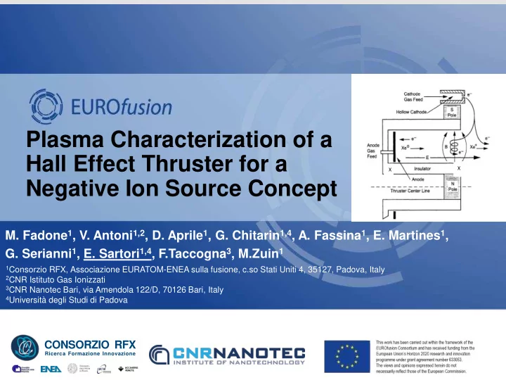
Plasma Characterization of a Hall Effect Thruster for a Negative Ion Source Concept

  • M. Fadone1, V. Antoni1,2, D. Aprile1, G. Chitarin1,4, A. Fassina1, E. Martines1,
  • G. Serianni1, E. Sartori1,4, F.Taccogna3, M.Zuin1
ACCIAIERIE VENETE

CONSORZIO RFX

Ricerca Formazione Innovazione

X X 1Consorzio RFX, Associazione EURATOM-ENEA sulla fusione, c.so Stati Uniti 4, 35127, Padova, Italy 2CNR Istituto Gas Ionizzati 3CNR Nanotec Bari, via Amendola 122/D, 70126 Bari, Italy 4Università degli Studi di Padova

slide-2
SLIDE 2

Novosibirsk - NIBS - 07/09/2018

C

Introduction

2

Novosibirsk - NIBS - 07/09/2018

  • EuroFusion enabling research EUF-ENR-17
  • Experimental studies of Hall Effect Thruster technology

modified to work in Hydrogen with energies compatible with the negative ion production

X X

D.M. Goebel, I. Katz, in Fundamentals and Electric Propulsion, (John Wiley & Sons, Inc., Hoboken, New Jersey),p.325-392

slide-3
SLIDE 3

Novosibirsk - NIBS - 07/09/2018

C

Introduction

3

Novosibirsk - NIBS - 07/09/2018

  • EuroFusion enabling research EUF-ENR-17
  • Experimental studies of Hall Effect Thruster technology

modified to work in Hydrogen with energies compatible with the negative ion production ATHENIS (Alternative Thruster Hall Effect Negative Ion Source Study) MCC PIC simulation Design and manufacturing Commissioning & design improvement (operation in nitrogen) Hydrogen plasma characterization NI production

X X

D.M. Goebel, I. Katz, in Fundamentals and Electric Propulsion, (John Wiley & Sons, Inc., Hoboken, New Jersey),p.325-392

y1 y2

slide-4
SLIDE 4

Novosibirsk - NIBS - 07/09/2018

C

Introduction

4

Novosibirsk - NIBS - 07/09/2018

  • EuroFusion enabling research EUF-ENR-17
  • Experimental studies of Hall Effect Thruster technology

modified to work in Hydrogen with energies compatible with the negative ion production ATHENIS (Alternative Thruster Hall Effect Negative Ion Source Study) MCC PIC simulation Design and manufacturing Commissioning & design improvement (operation in nitrogen) Hydrogen plasma characterization NI production y1 y2

slide-5
SLIDE 5

Novosibirsk - NIBS - 07/09/2018

C

Motivations

5

Novosibirsk - NIBS - 07/09/2018

X X

D.M. Goebel, I. Katz, in Fundamentals and Electric Propulsion, (John Wiley & Sons, Inc., Hoboken, New Jersey),p.325-392

  • Radial Magnetic Field with peak at the exit plane
  • Axial Electric Field to accelerate ions
  • Charge Neutralization through the cathode

Features of Hall Thruster concept:

slide-6
SLIDE 6

Novosibirsk - NIBS - 07/09/2018

C

Motivations

6

Novosibirsk - NIBS - 07/09/2018

X X

D.M. Goebel, I. Katz, in Fundamentals and Electric Propulsion, (John Wiley & Sons, Inc., Hoboken, New Jersey),p.325-392

  • embedded magnetic field filter to confine

energetic electrons before the plume

  • Cylindrical symmetry
  • possibility to control the axial energy of the

particles to the plasma plume

  • Very robust and reliable technology

(long term space missions)

  • Radial Magnetic Field with peak at the exit plane
  • Axial Electric Field to accelerate ions
  • Charge Neutralization through the cathode

Features of Hall Thruster concept: «Negative» features = Attractiveness for NI

slide-7
SLIDE 7

Novosibirsk - NIBS - 07/09/2018

C

Motivations

7

Novosibirsk - NIBS - 07/09/2018

X X

D.M. Goebel, I. Katz, in Fundamentals and Electric Propulsion, (John Wiley & Sons, Inc., Hoboken, New Jersey),p.325-392

  • embedded magnetic field filter to confine

energetic electrons before the plume

  • Cylindrical symmetry
  • possibility to control the axial energy of the

particles to the plasma plume

  • Very robust and reliable technology

(long term space missions)

  • Radial Magnetic Field with peak at the exit plane
  • Axial Electric Field to accelerate ions
  • Charge Neutralization through the cathode

Features of Hall Thruster concept: «Negative» features = Attractiveness for NI

slide-8
SLIDE 8

Novosibirsk - NIBS - 07/09/2018

C

Motivations

8

Novosibirsk - NIBS - 07/09/2018

X X

D.M. Goebel, I. Katz, in Fundamentals and Electric Propulsion, (John Wiley & Sons, Inc., Hoboken, New Jersey),p.325-392

  • possibility to control the axial energy of the

particles to the plasma plume

  • embedded magnetic field filter to confine

energetic electrons before the plume

  • Cylindrical symmetry
  • Very robust and reliable technology
  • Radial Magnetic Field with peak at the exit plane
  • Axial Electric Field to accelerate ions
  • Charge Neutralization through the cathode

Features of Hall Thruster concept: «Negative» features = Attractiveness for NI

  • hardly ever been used with hydrogen

(low pressure discharges cannot be achieved,

  • r axial energy cannot be tuned down)
  • high Te in the plume
  • gas flow is too high

Not «Negative» features = possible showstoppers for H- in HT:

  • heaviest noble gases are used

to provide high specific impulse

  • larger dimensions
  • large gas flow
slide-9
SLIDE 9

Novosibirsk - NIBS - 07/09/2018

C

Strategy

9

  • Develop a Hall effect thruster design to maximise “NI-attractive” requirements
  • Flexibility in the design to minimize the risks  modularity

(no ignition of the plasma, not optimal geometry, too high discharge pressure, …)

  • Characterization of Hydrogen plasma discharge in ~0.4Pa ()
  • (next) Try to measure negative ions generated from a caesiated sample

What we need:

  • Spatial axial profile outside the HT of plasma density n and electronic temperature

Te (in the plume)

  • Identify plasma species and their energy
  • Plasma stability in different conditions, and behaviour of anomalous transport

across the B field lines

Novosibirsk - NIBS - 07/09/2018

slide-10
SLIDE 10

Novosibirsk - NIBS - 07/09/2018

C

Outline

10

  • 1. Our recipe for a tasty Hall Effect Thruster (design)
  • 2. Manufacturing and commissioning of the thruster
  • 3. Operation in N2 (already different than noble gases)
  • 4. Operation in H2 – characterization of the plasma plume
  • 5. Summary & next steps
  • M. Fadone, E. Sartori, 07/09/2018
slide-11
SLIDE 11

Novosibirsk - NIBS - 07/09/2018

C

Hall Effect Recipe

11

Magnetic Field B

z, r

rLe << R (B>100 Gauss)

  • Radial magnetic field inside the channel
slide-12
SLIDE 12

Novosibirsk - NIBS - 07/09/2018

C

Hall Effect Recipe

12

Magnetic Field B

z, r

  • Radial magnetic field inside the channel
slide-13
SLIDE 13

Novosibirsk - NIBS - 07/09/2018

C

Hall Effect Recipe

13

Magnetic Field B

z, r

  • Radial magnetic field inside the channel
  • Modular approach for flexibility, NBImag

simulations

slide-14
SLIDE 14

Novosibirsk - NIBS - 07/09/2018

C

Hall Effect Recipe

14

Magnetic Field B

z, r

0.00 5.00 10.00 15.00 20.00

  • 40
  • 20

20

Magnetic Field [mT]

HALL PROBE MEASUREMENTS

  • Radial magnetic field inside the channel
  • Modular approach for flexibility, NBImag

simulations

  • Ferromagnetic material
  • hall probe measurement of Br in the channel

Ferromagnetic material

slide-15
SLIDE 15

Novosibirsk - NIBS - 07/09/2018

C

Hall Effect Recipe

15

Electric Field

Ez

slide-16
SLIDE 16

Novosibirsk - NIBS - 07/09/2018

C

Hall Effect Recipe

16

Electric Field

e-

  • Electric field between anode and hollow cathode

Anode

  • First thrusters with tungsten filaments as

emissive cathode (high power consumption and low life duration of the filament  Hollow cathode for space applications to increase the thruster life and low power consumption (benefit for space applications)

slide-17
SLIDE 17

Novosibirsk - NIBS - 07/09/2018

C

Hall Effect Recipe

17

Electric Field

e- Anode

Ez

  • Electric field between anode and hollow cathode
  • We decided to use a Tungsten filament cathode

as fastest «time-to-plasma» option despite their low reliability

  • Hollow cathode is anyway necessary for reliable
  • peration, stability, and to increase efficiency

W filament

slide-18
SLIDE 18

Novosibirsk - NIBS - 07/09/2018

C

Hall Effect Recipe

18

Cathode position

Ez

  • +

റ 𝐺 = 𝑟(𝐹+ റ 𝑤x 𝐶)

  • Electron tracing in vacuum to obtain ionization rate
  • Optimization of (z, r)
  • +

0V / 90V 0V / 250V

0 5 10 15

  • 20
  • 40
  • 60
  • 80

20 40 60 z (mm) r (mm)

slide-19
SLIDE 19

Novosibirsk - NIBS - 07/09/2018

C

Hall Effect Recipe

19

Gas flow

  • Minimize pressure out of the channel

H2

  • Plasma ingition condition at low hydrogen pressure

from PIC simulation

slide-20
SLIDE 20

Novosibirsk - NIBS - 07/09/2018

C

Hall Effect Recipe

20

Plasma discharge (hopefully) H2

slide-21
SLIDE 21

Novosibirsk - NIBS - 07/09/2018

C

Hall Effect Recipe

21

Plasma discharge (hopefully) H2

  • Electrostatic probes at discharge channel exit
  • Movable probe in the plume
slide-22
SLIDE 22

Novosibirsk - NIBS - 07/09/2018

C

Outline

22

  • 1. Our recipe for a tasty Hall Effect Thruster (design)
  • 2. Manufacturing and commissioning of the thruster
  • 3. Operation in N2 (already different than noble gases)
  • 4. Operation in H2 – characterization of the plasma plume
  • 5. Summary & next steps
slide-23
SLIDE 23

Novosibirsk - NIBS - 07/09/2018

C

Setup

23

  • PEEK gas channel
  • Gas Injection

Vacuum Side Air Side Mass flow Controller

Gas Injection

slide-24
SLIDE 24

Novosibirsk - NIBS - 07/09/2018

C

Setup

24

  • PEEK gas channel
  • Gas Injection

Vacuum Side Air Side

  • Injection Plate
  • Squared plate base
  • PEEK insulation rings
  • Central cylinder potential screw
slide-25
SLIDE 25

Novosibirsk - NIBS - 07/09/2018

C

Setup

25

Vacuum Side Air Side

  • Central cylinder
slide-26
SLIDE 26

Novosibirsk - NIBS - 07/09/2018

C

Setup

26

Vacuum Side Air Side

  • Central cylinder
  • Internal Quartz tube
slide-27
SLIDE 27

Novosibirsk - NIBS - 07/09/2018

C

Setup

27

Vacuum Side Air Side

  • Central cylinder
  • Internal Quartz tube
  • External Quartz tube

DISCHARGE CHANNEL WITH QUARTZ WALLS

slide-28
SLIDE 28

Novosibirsk - NIBS - 07/09/2018

C

Setup

28

Vacuum Side Air Side

  • Central cylinder
  • Internal Quartz tube
  • External Quartz tube
  • Ferromagnetic rings
slide-29
SLIDE 29

Novosibirsk - NIBS - 07/09/2018

C

Setup

29

Vacuum Side Air Side

  • Central cylinder
  • Internal Quartz tube
  • External Quartz tube
  • Ferromagnetic rings
  • External PEEK insulation
slide-30
SLIDE 30

Novosibirsk - NIBS - 07/09/2018

C

Setup

30

Vacuum Side Air Side

  • Central cylinder
  • Internal Quartz tube
  • External Quartz tube
  • Ferromagnetic rings
  • External PEEK insulation
  • Permanent magnets
  • Aluminum rings hosting the magnets
slide-31
SLIDE 31

Novosibirsk - NIBS - 07/09/2018

C

Setup

31

Vacuum Side Air Side

  • Central cylinder
  • Internal Quartz tube
  • External Quartz tube
  • Ferromagnetic rings
  • External PEEK insulation
  • Permanent magnets
  • Aluminum rings hosting the magnets
  • Boron Nitride cap
  • Boron Nitride plate
slide-32
SLIDE 32

Novosibirsk - NIBS - 07/09/2018

C

Setup

32

Hot cathode feedthroughs Optical fiber gas feedthrough RF feedthrough Pressure gauge … manipulator LOS

slide-33
SLIDE 33

Novosibirsk - NIBS - 07/09/2018

C

Setup

33

Hot cathode feedthroughs Optical fiber gas feedthrough RF feedthrough Pressure gauge … manipulator LOS

slide-34
SLIDE 34

Novosibirsk - NIBS - 07/09/2018

C

Outline

34

  • 1. Our recipe for a tasty Hall Effect Thruster (design)
  • 2. Manufacturing and commissioning of the thruster
  • 3. Operation in N2 (already different than noble gases)
  • 4. Operation in H2 – characterization of the plasma plume
  • 5. Summary & next steps
slide-35
SLIDE 35

Novosibirsk - NIBS - 07/09/2018

C

Operation in N2

35

  • N2 safer than H2
  • Molecular gas, Similar ionization energy
  • Through N2 experience, upgrades of the experiment

(substitution of melted parts, improvements of electric insulation)

  • Definition of the best cathode position
  • Determination of the main parameters which affect the

plasma discharge (Vdischarge, Ifilament, pchamber)

  • M. Fadone, E. Sartori, 07/09/2018
slide-36
SLIDE 36

Novosibirsk - NIBS - 07/09/2018

C

Operation in N2

36

Axial study of electronic density and temperature

Cathode position Cathode position

[1] D. Desideri and G. Serianni, “Four parameter data fit for Langmuir probes with nonsaturation of ion current”, Review of Scientific Instruments, Vol.69, n.6 (1998).

z

slide-37
SLIDE 37

Novosibirsk - NIBS - 07/09/2018

C

Operation in N2

37

  • n and Te raises with

Vdischarg

  • Vdischarge controlled

through Ifilament

  • Constant axial

profile of n and Te

  • Optimum mdot at

60sccm Axial study of electronic density and temperature Temperature and density vs discharge voltage

Cathode position Cathode position

[1] D. Desideri and G. Serianni, “Four parameter data fit for Langmuir probes with nonsaturation of ion current”, Review of Scientific Instruments, Vol.69, n.6 (1998).

z

  • +
  • +
slide-38
SLIDE 38

Novosibirsk - NIBS - 07/09/2018

C

Outline

38

  • 1. Our recipe for a tasty Hall Effect Thruster (design)
  • 2. Manufacturing and commissioning of the thruster
  • 3. Operation in N2 (already different than noble gases)
  • 4. Operation in H2 – characterization of the plasma plume
  • 5. Summary & next steps
slide-39
SLIDE 39

Novosibirsk - NIBS - 07/09/2018

C

Operation in hydrogen

39

Objectives

  • Plasma characterization far from the exit of

discharge channel

  • Find the minimum operational pressure to maximize

the mean free path (for H0, H-)

slide-40
SLIDE 40

Novosibirsk - NIBS - 07/09/2018

C C

Operation in hydrogen

40

Objectives

  • Plasma characterization far from the exit of

discharge channel

  • Find the minimum operational pressure to maximize

the mean free path (for H0, H-) Comments

  • Almost constant ion density profile in the plume
  • Te profile decays beyond the cathode
  • ~1016 m-3 density (~1017 m-3for N2)

Axial study of electronic density and temperature z

slide-41
SLIDE 41

Novosibirsk - NIBS - 07/09/2018

C

Double electron population

41

[1]M. A. Lieberman, A. J. Lichtenberg, «Principles of Plasma Discharges and Materials Processing», Wiley-Interscience, 2° edition, cap. 6 and 11] [2] S. Gallian, J. Trieschmann, T. Mussenbrock, R. P. Brinkmann, and W. N. G. Hitchon, “Analytic model of the energy distribution function for highly energetic electrons in magnetron plasmas”, Journal of Applied Physics 117, 023305 (2015)

  • Double electronic population identified

in few cases near the exit plane or far away

  • Phenomenum still under investigation

(Magnetic field influence near the exit plane, acceleration of thermal electrons to compensate H+ energetic ions far from the device [2])

  •  study for plasma instabilities

)

Electron energy probability function gp versus εe [1] measured at the exit of the discharge channel for two cases at different anode voltages:

slide-42
SLIDE 42

Novosibirsk - NIBS - 07/09/2018

Motivation: Plasma instability, mainly ExB electron drift induced1, believed to determine cross-field electron transport and reduce Hall thrusters perfomances Preliminary analysis of electron density fluctuations highlights the presence of various plasma instabilities Spectral properties depend on plasma condition (power

  • perating level) and positions

[1] Lafleur et al., Phys. Plasmas 25 (2018)

Z=0cm, Ifil=6.7A Z=4cm, Ifil=6.7A Z=4cm, Ifil=6.1A

C

Plasma instability analysis

42

slide-43
SLIDE 43

Novosibirsk - NIBS - 07/09/2018

Two-point technique used to determine exp. dispersion relation (phase and group velocity) for instability identification.

Z=0cm, Ifil=6.7A Z=4cm, Ifil=6.7A Z=4cm, Ifil=6.1A

C

Plasma instability analysis

43

slide-44
SLIDE 44

Novosibirsk - NIBS - 07/09/2018

Aliasing affects wavelength determination (small scale instability). New diagnostic system based on complete azimuthal array of Langmuir probes, for high mode number analysis realized and planned to be used in the next future.

C

Plasma instability analysis

4

slide-45
SLIDE 45

Novosibirsk - NIBS - 07/09/2018

[M. Seidl et al, “Negative surface ionization of hydrogen atoms and molecules”, Journal of Applied Physics 79, 2896 (1996)]

Thermal screen (optional)

C

Caesiated sample insertion

Conclusions and next steps

Next:

  • Installation of optic fiber for

spectroscopic measurements

  • Pre-caesiated sample

(Alternatively, in situ by use of SAES dispensers)

  • Hollow cathode to replace

tungsten filament

  • The specifically designed a Hall effect

plasma generator was successfully

  • perated in hydrogen
  • In the plume, thin plasma with n

3∙1016 m-3 is found, with Te 2-2.5 eV

slide-46
SLIDE 46

Novosibirsk - NIBS - 07/09/2018

C

  • H2 simulations shown that HT can generate excited H0
  • HT in house to study the possibility to generate H-
  • Experience through N2 injection helped to understand the response of the thruster

and the upgrades to avoid the failures encountered during this process

  • Characterization of plasma discharge in H2
  • Constant axial density profile (~1016 m-3 for H2,~1017 m-3for N2)
  • Slow T decay along z-axis until 2eV
  • Vanode, Ifilament and pchamber main parameters which affect the plama
  • Next phase collecting H- and improving plasma analysis diagnostic

Summary