
SLIDE 1
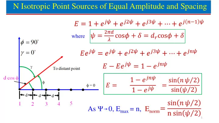
N Isotropic Point Sources of Equal Amplitude and Spacing
where
As Ψ 0, Emax = n, Enorm
1
N Isotropic Point Sources of Equal Amplitude and Spacing where As - - PowerPoint PPT Presentation
N Isotropic Point Sources of Equal Amplitude and Spacing where As 0, E max = n, E norm 1 Radiation Pattern of N Isotropic Elements Array Array Factor First SLL = 20log0.22 = -13.15dB Radiation Pattern for array of n isotropic radiators of
1
Radiation Pattern for array of n isotropic radiators of equal amplitude and spacing.
Array Factor
2
3
4
5
6
7
8
9
10
(a) Radiation Pattern of linear array of 5 isotropic point sources of equal amplitude and λ/2 spacing (a) all 5 sources ON (b) one source (next to the edge) OFF (c) one source (at the centre) OFF, and (d) one source (at the edge) OFF (b) (c) (d)
11
12
13
14
15
16
17
18
19
20
21
22