MULTISCALE MODELING OF COVALENTLY GRAFTED NANOPARTICLE/POLYMER - - PDF document

multiscale modeling of covalently grafted nanoparticle
SMART_READER_LITE
LIVE PREVIEW

MULTISCALE MODELING OF COVALENTLY GRAFTED NANOPARTICLE/POLYMER - - PDF document

18 TH INTERNATIONAL CONFERENCE ON COMPOSITE MATERIALS MULTISCALE MODELING OF COVALENTLY GRAFTED NANOPARTICLE/POLYMER NANOCOMPOSITES S Yang 1 , J Choi 1 , S Yu 1 , M Cho 1 * 1 School of Mechanical and Aerospace Engineering, Seoul National


slide-1
SLIDE 1

18TH INTERNATIONAL CONFERENCE ON COMPOSITE MATERIALS

1 Introduction With a recent advancement of nanomanufacturing technology, various types

  • f

nanocomposites materials have been developed and widely applied to multifunctional design for specific applications. When the size of nano-sized filler decreases to the radius of gyration of matrix polymer or even less than it, the motion of the matrix molecules surrounding the nano filler is critically immobilized and a highly densified adsorption layer is formed as an addition phase that constitutes the nanocomposites microstructure[1]. The importance and contribution of the interphase, thus, has been the major concern of the design and analysis of polymer nanocomposites to achieve multifunctionality and various researches have been followed[2]. In order to increase the load transfer efficiency and to prevent filler aggregation that critically affects the

  • verall properties of the nanocomposites, various

types of functionalization (covalent or non-covalent grafting of the nanoparticle) have been applied to the synthesis manufacture of polymer nanocomposites. In order to establish structure property relationship

  • f nanoparticulate composites, molecular dynamics

and some multiscale simulation approaches that bridge atomistic simulations and conventional continuum models have been widely applied and suggested to identify filler size effect by defining the interphase as an additional phase[2]. Most of the previous studies that have dealt with the filler size effect and interphase, however, focused only on nonfunctionalized cases. Against the above mentioned background, this study performs molecular dynamics simulation and proposes an efficient multiscale model to characterize filler size- dependent elastic stiffness of nanocomposites and to establish structure-property relationship

  • f

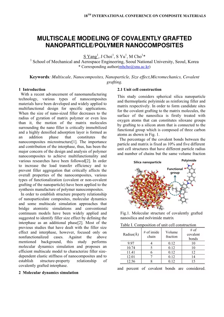
covalently grafted interphase. 2 Molecular dynamics simulation 2.1 Unit cell construction This study considers spherical silica nanoparticle and thermoplastic polyimide as reinforcing filler and matrix respectively. In order to form candidate sites for the covalent grafting to the matrix molecules, the surface of the nanosilica is firstly treated with

  • xygen atoms that can constitutes siloxane groups

by grafting to a silicon atom that is connected to the functional group which is composed of three carbon atoms as shown in Fig. 1. The percentage of the covalent bonds between the particle and matrix is fixed as 10% and five different unit cell structures that have different particle radius and number of chains but the same volume fraction and percent of covalent bonds are considered. Table I. Composition of unit cell construction

Radius(Å) # of imide chain Volume fraction # of covalent bonds 9.97 4 0.12 10 10.74 5 0.12 10 11.41 6 0.12 12 12.01 7 0.12 14 12.56 8 0.12 15

Silica nanoparticle Polyimide Functional group

Fig.1. Molecular structure of covalently grafted nanosilica and polyimide matrix

MULTISCALE MODELING OF COVALENTLY GRAFTED NANOPARTICLE/POLYMER NANOCOMPOSITES

S Yang1, J Choi1, S Yu1, M Cho1*

1 School of Mechanical and Aerospace Engineering, Seoul National University, Seoul, Korea

* Corresponding author(mhcho@snu.ac.kr)

Keywords: Multiscale, Nanocomposites, Nanoparticle, Size effect,Micromechanics, Covalent grafting.

slide-2
SLIDE 2

Details of the cell construction are arranged in Table I. 2.2 Simulation procedures Following the cell composition, all the initial nanocomposites unit cells are constructed as amorphous structure to which one pristine silica nanoparticle is embedded. Then the surface silicon atoms of the silica that have free radical that can be functionalized are treated with oxygen atoms. Among all the treated oxygen atoms, the number of candidates that can have covalent bonds to the matrix molecules are counted at the 10% of covalent bonding ratio and the position of the candidate atoms are randomly chosen. Then, the candidate

  • xygen atoms are treated with Si-(CH2)3 functional

units where the last carbon atom acts as the linker of the covalent grafting. All the simulations are performed using Material Studio 5.0 package with COMPASS forcefield[3]. After treating the functional units to the surface of the silica, all the close contacts between the carbon atom of the functional group and the carbon atom of the benzene ring of polyimide are checked and the distance between each contacts are monitored. Then, the contacts within the cut off limit of 6 Å are covalently bonded to each other. During the new covalent bonding process, all the ring catenation and spearing are prevented to prevent unrealistic chemical structure. After all the candidate carbon atoms in functional groups are bonded to the matrix molecules, the unit cells are minimized to their minimum potential energy state using the conjugate gradient method. Before production run to calculate the elastic stiffness, all the nanocomposites unit cells are equilibrated at 600K and 1 atm for 100ps followed by an additional equilibration at 300K and 1atm for 900ps via an isothermal-isobaric(NPT) ensemble

  • simulations. The elastic constants are calculated

from strain fluctuation method combined with a constant stress ensemble(NσT) simulation

  • f

Parrinello-Rahman with 10000 strain fluctuations monitored from 100ps of the NσT simulations after 500ps of additional equilibration step via the NσT

  • simulations. For computational accuracy, all the

elastic constants are averaged over five different production runs. 2.3 Simulation results The elastic moduli obtained from the present molecular dynamics simulations are compared with the elastic moduli of the nanocomposites without any surface treatment demonstrated in our pervious

  • works. By applying only 10% of covalent grafting,

the elastic moduli of the nanocomposites increases by 171% and 190% compared with the elastic modulis of non-functionalized nanocomposites and pure polyimide matrix, repectively. One major finding from the covalently grafted nanocomposites unit cell is that the elastic moduli of the nanocomposites still exhibits the filler size dependency that has ever been demonstrated from non-functionalized nanocomposites in our previous work[2]. The variation of the elastic moduli with respect to the particle radius variation, however, varies with a more slowly decaying manner than the non-functionalized nanocomposites. From the variation obtained from the present MD simulation results is that the filler size dependency on elastic moduli can appear from much larger nanoparticle which has been found to have no size effect unless the surface of the nanoparticle is covalently grafted to the matrix polymer. By increasing the percent of covalent grafting to the matrix molecules, it is expected that the range of the filler size dependent elastic moduli will further be enlarged up to ~10nm scale where typical experimental approaches are available. 3 Micromechanics bridging model 3.1 Multi inclusion model In order to describe the filler size-dependent elastic stiffness of the nanocomposites with the covalent Table II. Elastic moduli of nanocomposites with and without covalent grafting

Radius(Å) E(GPa) G(GPa) 0%[2] 10% 0%[2] 10% 9.97 4.66 5.45 1.74 2.03 10.74 4.20 5.46 1.54 2.05 11.41 3.99 4.99 1.45 1.88 12.01 3.81 4.78 1.38 1.79 12.56 3.60 4.69 1.30 1.76 Matrix 2.44 2.44 0.88 0.88

slide-3
SLIDE 3

grafting at the interface, a multi inclusion model[4] based on the Eshelby solution to the inclusion problem is considered. In this model, a mulphase particle is assumed to be embedded into an infinite medium that has yet unknown elastic stiffness. The appropriateness of this model is its ability to consider multiple layered inclusion and usefulness to account for the non-dilute distribution condition. To describe the interphase that has covalently grafted molecular structure, the multi inclusion is defined as a three-phase structure consists of particle, matrix, and interface. The closed form solution of the effective elastic stiffness C, is then given as ,

 

1 N N inf r r r r r=1 r=1

f f

                           

 

C C I S I Φ I S Φ (1) where

inf

C is the stiffness of the infinite medium,

r

f is the volume fraction of rth constituent, I is the

identity tensor, S is the fourth-order Eshelby’s tensor[5] of the spherical inclusion and

r

Φ is the

fourth-order tensor given as:

 

1 1 r inf r inf  

       Φ C C C S

(2) where,

r

C is the fourth-order stiffness tensor of the

rth constituent. In Eqs.(1~2), all the quantities except the volume fraction and stiffness of the interphase can be

  • btained from the molecular dynamics simulations.

Consequently, the key process to utilize Eq.(1) to predict the elastic stiffness of the nanocomposites is to decide these two quantities. Following the bridging process suggested in ref[2], the volume fraction of the interface is obtained from the radial density distribution of the surrounding

  • matrix. In the density distribution, it is found that the

thickness of the highly densified region near the surface of the nanoparticle is almost 5 Å regardless

  • f the filler size.

When the volume fraction of the interface is

  • btained, there exists only one quantity-stiffness of

the interphase-that should be calculated to utilize Eqs(1~2). In order to calculate the stiffness of the interphase, the closed form solution in Eq.(1) can be rearranged as function of the stiffness of the interface given as

 

 

1 1 1 i inf i inf

f

  

           C C I B C CS S I S

(3)

 

p p m m 1 inf p p m m

( )( ) ( ) f f f f

       B I S I Φ Φ C C I S Φ Φ

. (4) Assuming that the interface elastic stiffness is isotropic, both the Young’s modulus and the shear modulus can be obtained from Eq.(4) and can be defined as a function of the particle radius. Once these two quantities are defined, effective elastic stiffness of the nanocomposites can be effectively estimated from Eq.(1) with accurate consideration of the grafted interphase and filler size dependency. The young’s modulus and the shear modulus of the interphase obtained from Eq.(3~4) are depicted in

  • Fig. 2 and compared with the modulus of non-

grafted interphase depicted in ref[2] and of the pure polyimide matrix. By applying 10% of grafting, the elastic stiffness of the interface is prominently enhaced and gradually decreases as the filler radius

  • increases. Thus, it can be concluded that the direct

covalent grafting of the nanoparticle to the polymer matrix can be a promising way to increase filler size- dependent elastic properties of the nanocomposites.

9 10 10 11 11 12 12 13 13 14 14 15 15 2 4 6 8 10 10 12 12

Particle R Radi dius us( ) Å Interphase Y terphase Young's

  • ung's modul
  • dulus

us(G (GPa)

10% grafted 10% grafted 0% g 0% graft afted Mat Matrix

(a) Young’s modulus

9 10 10 11 11 12 12 13 13 14 14 15 15 1 2 3 4 5 6

Particle R Radi dius us( ) Å Interphas phase s e shear ear modulus(GPa)

10% grafted 10% grafted 0% g 0% graft afted Mat Matrix

(b) Shear modulus Fig.2. Elastic modulus of the interphase.

slide-4
SLIDE 4

In order to compare the overall elastic modulus change of the present grafted nanocomposites with those of the non-grafted cases at various particle radius, both the Young’s modulus and the shear modulus of the interface is fitted into a function of the filler size as, 2.44 45.68exp( 0.17 )

int P

E r    and 0.88 11.06exp( 0.14 )

int P

G r    for the Young’s modulus and the shear modulus respectively. Then, the elastic stiffness of the nanocomposites at various particle radius are obtained and compared with the results from MD simulations.

  • Fig. 3 depects the variation of the Young’s

modulus and the shear modulus

  • f

the nanocomposites at various particle radius with and without covalent grafting. By 10 % of covalent grafting, the range of the particle radius that shows size effect on the elastic properties is broadened. 3 Conclusion In this study, an efficient multiscale bridging model is applied to characterize covalently grafted nanoparticulate polymer nanocomposites. By adding 10% of covalent bonds at the interface, the elastic stiffness of the interphase has been prominently enhanced and the range of the particle size has been

  • broadened. By defining the interphase stiffness as a

function of the particle size, the size dependency tailored by the covalent grafting has been efficiently described in micromechanics-based bridging model with accuracy. Acknowledgement This research was supported by WCU(World Class University) program through the National Research Foundation of Korea funded by the Ministry of Education, Science and Technology *(R31-2008-000-10083-0) References

[1] Cho. J., Josh. M. S., and Sun. C. T., “Effect of

inclusion size on mechanical properties of polymeric composites with micro and nanoparticles,” Compos Sci Technol, Vol.66, No.13, 2006, pp.1941-1952.

[2] S. Yang, M. Cho “A scale bridging method for

nanoparticulate polymer nanocomposites and their non-dilute concentration effect,” Appl.

  • Phys. Lett, Vol. 94, pp.223104, 2009.

[3] Accelrys Inc, San Diego, www.accelrys.com [4] M. Hori, S. Nemat-Nasser , “Double-

inclusion model and overall moduli of multiphase composites,” Mechanics

  • f

Materials 1993, Vol. 14, pp.189-206.

[5] Eshelby JD, “The determination of the

elastic field of and ellipsoidal inclusion and related problems,” Proc Roy Soc London 1957; Series A, pp. 241-398

10 10 15 15 20 20 25 25 30 30 3 4 5 6 7 8

Pa Part rticle Ra Radius( ) Å Young' ung's m modul

  • dulus(GPa)

Present bridg Present bridging m ng model:10% grafted

  • del:10% grafted

MD:10% g MD:10% graft afted Present bridg Present bridging m ng model:0% grafted

  • del:0% grafted

MD:0% gr MD:0% graft afted Mor Mori-T

  • Tana

anaka

(c) Young’s modulus

10 10 15 15 20 20 25 25 30 30 1 1.5 1.5 2 2.5 2.5 3

Pa Part rticle Ra Radius( ) Å Shear ear modul dulus us(GPa)

Pr Pres esent bri ent bridgin dging m model

  • del:10% gr

:10% graft afted MD MD:10 :10% grafted grafted Pr Pres esent bri ent bridgin dging m model

  • del:0% gra

:0% grafted ted MD MD:0% :0% g grafted afted Mori ri-T

  • Tan

anak aka

(d) Shear modulus Fig.2. Elastic modulus of the nanocomposites.