Mu2e Protection Collimator, PC Andy Stefanik January 19, 2016 - - PowerPoint PPT Presentation
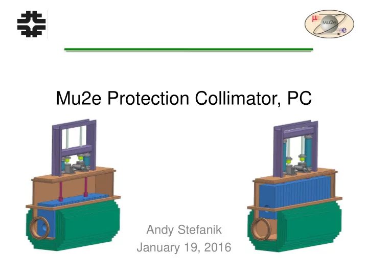
Mu2e Protection Collimator, PC Andy Stefanik January 19, 2016 Topics Requirements Basic Physics Engineering Integration Protection Collimator, PC Stand Installation Schedule To-do list January 19, 2016 2
Topics
- Requirements
- Basic Physics
- Engineering
- Integration
- Protection Collimator, PC
- Stand
- Installation
- Schedule
- To-do list
January 19, 2016 2
Requirements
- PHYSICS:
- Mu2e Document 2897. http://mu2e-docdb.fnal.gov:8080/cgi-bin/ShowDocument?docid=2897
- The Compliance Report is Mu2e Document 6513.
http://mu2e-docdb.fnal.gov:8080/cgi-bin/ShowDocument?docid=6513
- The PC complies with these requirements.
- ENGINEERING:
- Mu2e Document 2902. http://mu2e-docdb.fnal.gov:8080/cgi-bin/ShowDocument?docid=2902
- The PC complies with the requirements that are not
marked TBD.
January 19, 2016 3
Integration
- PC physical integration into the experiment is
accomplished using the Mu2e CAD Integration Model, F10002515.
January 19, 2016 4
PC cross sections
January 19, 2016
- Initial concept…
- Went from this to…
5
PC cross sections
January 19, 2016
- Moveable core “in” Moveable core “out”
Stationary core Moveable core Vacuum vessel Up-down drive
6
PC core dimensions
January 19, 2016
8 cm (3.15”) 50 cm (19.7”)
7
PC core dimensions
January 19, 2016
101.6 cm (40”)
8
Beam scan aperture dimensions
January 19, 2016
CF ID 19.84 cm (7.812”) 22.22 cm (8.75”) 20.955 cm (8.25”) The requirement is 20.83 cm (8.2”).
9
Beam scan aperture is centered on the beam.
Stationary core
- The stationary core is outside the vacuum vessel.
- 316L stainless steel weldment.
- Weight: 2,200 pounds.
- Overall dimensions (W x H x L): 515 x 454 x 1,016 mm
(20.25” x 17.875” x 40”)
January 19, 2016 10
Moveable core
- The moveable core is inside the vacuum vessel.
- 316L stainless steel weldment.
- Weight: 1,245 pounds.
- Overall dims (W x H x L): 209.55 x 355.6 x 1,031.1 mm
(8.25” x 14” x 40.6”)
January 19, 2016 11
Vacuum vessel
- Outside dimensions (W x H x L): 254 x 654 x 1,162 mm
(10” x 25.75” x 45.75”)
- 316L weldment.
- 770 pounds.
January 19, 2016 12
Vacuum vessel - Fabrication
- Box
- 635 pounds.
- 100% seal welded inside.
- Intermittent welds outside.
- Notched edges all around.
January 19, 2016 13
Vacuum vessel: Fabrication
- Top
- 135 pounds.
- Edge welded to the box.
- Not shown: A small port on top. Might use it for a gauge,
leak checking.
- Option: Bolted top with indium seal.
January 19, 2016 14
Vacuum vessel: Loads
- Design:
- Full external vacuum, 15 psi, with blank-off flanges on all of the
ports, including the two beam ports.
- Weight of the vacuum vessel, moveable core, and up-down drive
components, ~ 2.200 pounds, reacted along the two long surfaces of the center reinforcing plate.
- Lifting:
- Weight of the vacuum vessel, moveable core, and up-down drive
components, ~ 2,220 pounds, reacted at the lift points.
- Operating:
- Same as the Design Loads except for the vacuum load on the
two beam ports.
January 19, 2016 15
Vacuum vessel: Bellows
- Edge welded with CF flanges
- Bellows: 347 stainless steel
- CF Flanges: 304L stainless steel
- Gasket: copper
- 3” OD x 2” ID. The diameter might decrease in the final
design.
- Extended length per segment: 1.05
- Compressed length per segment: 0.2
- Stroke per segment: 1.05 – 0.2 = 0.85”
- Required stroke: 8.25”
January 19, 2016 16
Vacuum vessel: Bellows
- Required number of segments: 8.25”/0.85” per segment =
9.7 → Use 10 segments.
- Ultimate number of cycles with 10 segments: 10,000
- Expected number of cycles in the Mu2e experiment: 50
the first year and then roughly 1 per month after that. So the expected number of cycles is 100 to 200 over the lifetime of the experiment. Thus, we have a large margin
- n the number of cycles using the standard bellows.
- If we do not operate the bellows over its maximum range
by using 12 segments and operating over the 10 segment range, the ultimate number of cycles remains at 10,000.
January 19, 2016 17
Vacuum vessel: Bellows
- From the vendor: The bellows will not squirm while under
vacuum provided the flanges on the ends of the bellows are secure. However, if you vent the bellows to atmosphere while it is compressed, it will squirm.
- We will discuss bellows squirm with the beamline vacuum
group and follow-up with the vendor. We will add an internal cylindrical guide in each bellows to prevent squirm if needed in the beamline vacuum system.
- Bellows diameter might decrease. Connecting rod
diameter might increase.
January 19, 2016 18
Vacuum vessel: up-down drive
- Try to use a commercial linear lifter.
- MDC – 20 pounds maximum.
January 19, 2016
- LSM Ballscrew (Kurt J Lesker):
Maximum axial load is 250 N (55 pounds) with a 6” clear bore and with a 300 mm maximum stroke. The full vacuum load is 425 pounds. The total lifting capacity of the lifter is 480 pounds which is less than half the moveable core weight.
- At this point, we are designing our
- wn up-down drive. We continue to
look for a commercial unit.
19
Vacuum vessel: up-down drive
- We are currently using a stainless steel screw jack.
- Other options are a scissors jack or a four-post jack. I
have not found either of these jacks in stainless steel and with sufficient capacity yet and I don’t think I will.
- The screw jack is lubricated with grease. We need to
purchase the jack with the rad-approved grease used in
- ur beamlines or replace the OEM grease with our
grease after we get it. Alternatively, we can purchase the jack with a rad-hard grease that is the vendor standard.
January 19, 2016 20
Vacuum vessel: up-down drive
- Core in the beam-on position
January 19, 2016 21
Edge-welded bellows Worm gear machine screw jack with travelling nut Jack cross beam Frame Guards attach to the frame Spherical washer Connecting rod with pin connection at each end Extra internal volume at each beamline port to aid pump down
Vacuum vessel: up-down drive
- Core in the beam-scan position
January 19, 2016 22
54.8 cm (21.6”)
Vacuum vessel: up-down drive
- January 19, 2016
Chart courtesy of Nook Industries Column strength for stainless steel jacks: PC load on one jack = 700 pounds max with 20” max screw length.
23
CAUTION: Chart does not include a design factor.
Vacuum vessel: up-down drive
- Jack info:
- Capacity: 0.66 tons = 1,320 pounds.
- Gear ratio: 24:1 (20:1 or greater ratio ACME machine screw jacks
can be considered self-locking in the absence of vibration.)
- Turns of the worm gear per inch of travel: 96
- Torque to raise 1 pound: 0.015 in-Lbs
- Lifting screw diameter: 1”
- Maximum allowable input: 0.5 horsepower
- Maximum input torque: 14 in-Lbs
- Maximum load at 1750 rpm: 1320
- Duty cycle limit: 25% (75% time off)
January 19, 2016 24
Vacuum vessel: up-down drive
- Horsepower required to operate the jack with no
arrangement of gearbox efficiencies included:
- Load per jack: 700 Lbs
- Input rpm: (96 turns of the worm gear per inch of travel) x (8.25
inches of travel) / 10 minutes = 80 rpm
- Torque: (0.015 in-Lbs/Lb) x (700 Lbs) = 10.5 in-Lbs
- Horsepower per jack: 0.013 (0.006 hp with the 6:1 gear ratio)
January 19, 2016 25
Vacuum vessel: up-down drive
- Driver options:
- Electric motor
- Pneumatic motor
- Pneumatic cylinder
- The pc environment:
- Magnetic field: 350 gauss
- Radiation level: TBD
- Residual radiation: TBD
January 19, 2016 26
Vacuum vessel: up-down drive
- The current plan is to use an electric motor to drive the
jacks.
- Working with others on the motor:
- Dan Schoo: “We can supply you with the limit switches, a motor
controller and a means of controlling it through ACNET. Once the motor is specified we can help find one and order it.”
- Dan Schoo: “I have never done any research or read any data on
- perating AC induction motors in a strong magnetic field. I
suspect that a 350 gauss field would freeze any motor.”
- Nikolai Andreev (TD, mech eng) is looking at motors for the
rotating collimator mid-way through the Transport Solenoid that work near the solenoid, so he might be able to help us on motor selection or solutions
January 19, 2016 27
Vacuum vessel: up-down drive
- Using a motor in the 350 gauss magnetic field is not
settled yet. In the end, we may have to locally shield it.
- The motor might be equipped with a brake.
- A torque-limiting coupling will be used.
January 19, 2016 28
Vacuum vessel: Details
- The center of the aperture bore in the moveable core will
be referenced to alignment fiducials on the stationary core.
- The PC will have brackets to mount Beam Loss Monitors.
- AD will pump down the PC along with the beamline. We
have started working with the AD vacuum group on a plan. We might have to add a large pump-out port on the vacuum vessel.
- The PC has extra internal volume at the beam line ports to
aid pump down, as shown on slides 20 and 21.
- The vacuum vessel is located to the stationary core.
January 19, 2016 29
Vacuum vessel: Assembly
- The connecting rod is seal welded to the upper conflat
- flange. The seal weld must be cut out to replace a bellows.
January 19, 2016 30
Seal weld Bellows diameter might
- decrease. Connecting rod
diameter might increase
PC Lift Points
- The stationary core has two lift points. These lift points are
designed to lift the completely assembled PC.
- The vacuum vessel will either have one integral lift point or
two separate lift points. The lift point(s) are designed for the weight of the vacuum vessel, the moveable core, and the up-down drive. The stationary core shall not be connected to the vacuum vessel when using the vacuum vessel lift points.
January 19, 2016 31
At two points on the vacuum vessel.
Stand
- January 19, 2016
32
- We will use the stand
design that AD has for the beamline magnets. Rob Reilly sent me this photo of the stand. The stand is black in the photo.
- The PC stand will be
made with 6061-T6 aluminum.
- The PC stand will have
its own Engineering Note.
Miniboone line
Stand
- The AD magnet stands will have an adjuster on top; the
adjuster is shown below. The PC will not have the adjuster.
January 19, 2016 33
Installation
- The PC will be installed in the same way as the magnets
will be installed.
- From Rob Reilly: “I intend to have these on stands with
Hilman rollers, to bring the magnets in on the monorail and set them on their stands in the aisle, then roll them into place. Since we have to move the M4 line magnets in two directions I will have them on rotating rollers.”
- The protection collimator will be installed on its stand,
rolled into the beamline, and aligned using the fiducials
- n the stationary core.
- After alignment, the electrical will be hooked up and the
up-down drive will be tested.
January 19, 2016 34
Schedule
- January 19, 2016
35
To-do List
- Review all of the final requirements.
- Continue working with the AD Groups.
- Complete PC final design.
- Internal Project review of the PC final design.
- Review the schedule.
- Analysis and Engineering Note for the PC.
- Analysis and Engineering Note for the stand.
- Analysis and Engineering Note for the vacuum vessel
spreader bar if it has two lift points.
- Complete the Fermilab Engineering Manual Risk
Assessment.
January 19, 2016 36