
SLIDE 1
Modular cavity status and test plan Daniel Bowring Overview RF Measurements Experimental Plan Photos
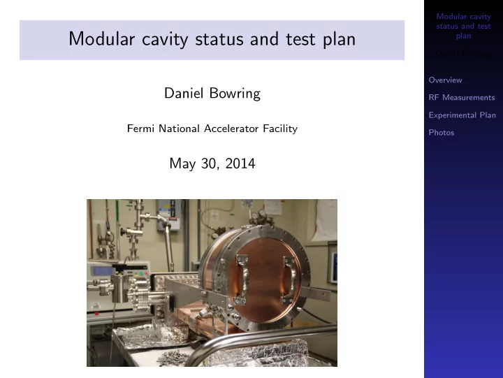
Modular cavity status and test plan
Daniel Bowring
Fermi National Accelerator Facility
May 30, 2014
Modular cavity status and test plan plan Daniel Bowring Overview - - PowerPoint PPT Presentation
Modular cavity status and test Modular cavity status and test plan plan Daniel Bowring Overview Daniel Bowring RF Measurements Experimental Plan Fermi National Accelerator Facility Photos May 30, 2014 Overview Modular cavity status and
Modular cavity status and test plan Daniel Bowring Overview RF Measurements Experimental Plan Photos
Daniel Bowring
Fermi National Accelerator Facility
May 30, 2014
Modular cavity status and test plan Daniel Bowring Overview RF Measurements Experimental Plan Photos
been verified.
delivered to FNAL yet. Endplate flanges are mechanically weak, making the RF joint unstable.
solved problem.
experimental plan? (Plus: photos.)
Modular cavity status and test plan Daniel Bowring Overview RF Measurements Experimental Plan Photos
Modular cavity status and test plan Daniel Bowring Overview RF Measurements Experimental Plan Photos
(Quantitative data on next slide.)
Modular cavity status and test plan Daniel Bowring Overview RF Measurements Experimental Plan Photos
Property Sim. Meas. Notes Frequency (MHz) 804.99 804.65 Measurement w/o vacuum Unloaded Q0 25602 24383 Loaded QL 11861 15141 Not under- stood. Bad RF adapter?
3040 50 60 7080 90 804.30 804.35 804.40 804.45 804.50 804.55 804.60 804.65 804.70 Frequency (MHz) 3040 50 60 7080 90 Torque (inch-pounds) 16000 18000 20000 22000 24000 Q0 3040 50 60 7080 90 0.6 0.7 0.8 0.9 1.0 1.1 beta
Modular cavity status and test plan Daniel Bowring Overview RF Measurements Experimental Plan Photos
◮ Full design analysis and recovery discussion took place
yesterday evening: https://indico.fnal.gov/contributionDisplay. py?sessionId=16&contribId=133&confId=8326
◮ Minimally invasive plan gets the cavity to FNAL ASAP. ◮ Staged “upgrades” possible if the minimally invasive fix
proves insufficient.
Modular cavity status and test plan Daniel Bowring Overview RF Measurements Experimental Plan Photos
Modular cavity status and test plan Daniel Bowring Overview RF Measurements Experimental Plan Photos
The modular cavity allows us to collect “clean” data.
◮ Mimics coupling strategy
in a cooling channel.
◮ Strongest surface E-field
(by 5×) is on-axis.
We can test different materials and surface treatments.
◮ Beryllium vs. copper ◮ Half-hard vs.
fully-annealed Cu
◮ Chemical polishing vs.
electropolishing
◮ Other materials?
Modular cavity status and test plan Daniel Bowring Overview RF Measurements Experimental Plan Photos
Sequence of runs
plates, B=3/0
plates, B=0/3
B=TBD
alloy plates, etc.)
What does a single run look like?
gradient
Notation: B=3/0 denotes a run at 3 T followed by a run at 0 T.
Modular cavity status and test plan Daniel Bowring Overview RF Measurements Experimental Plan Photos
ASC: High-res scanner ASC: Digital microscope
Modular cavity status and test plan Daniel Bowring Overview RF Measurements Experimental Plan Photos
Modular cavity status and test plan Daniel Bowring Overview RF Measurements Experimental Plan Photos
Modular cavity status and test plan Daniel Bowring Overview RF Measurements Experimental Plan Photos
Modular cavity status and test plan Daniel Bowring Overview RF Measurements Experimental Plan Photos
Modular cavity status and test plan Daniel Bowring Overview RF Measurements Experimental Plan Photos
Modular cavity status and test plan Daniel Bowring Overview RF Measurements Experimental Plan Photos
Modular cavity status and test plan Daniel Bowring Overview RF Measurements Experimental Plan Photos