MODELLING THE BLAST BEHAVIOUR OF FIBRE METAL LAMINATES C. Soutis 1 - - PDF document

modelling the blast behaviour of fibre metal laminates
SMART_READER_LITE
LIVE PREVIEW

MODELLING THE BLAST BEHAVIOUR OF FIBRE METAL LAMINATES C. Soutis 1 - - PDF document

18 TH INTERNATIONAL CONFERENCE ON COMPOSITE MATERIALS MODELLING THE BLAST BEHAVIOUR OF FIBRE METAL LAMINATES C. Soutis 1 *, G. Mohamed 1 1 Department of Mechanical Engineering, University of Sheffield, Sheffield, United Kingdom * Corresponding


slide-1
SLIDE 1

18TH INTERNATIONAL CONFERENCE ON COMPOSITE MATERIALS

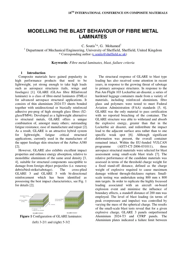
1 Introduction Composite materials have gained popularity in high performance products that need to be lightweight, yet strong enough to take high loads such as aerospace structures (tails, wings and fuselages) [1]. GLARE (GLAss fibre REinforced laminate) is a class of fibre-metal laminates (FMLs) for advanced aerospace structural applications. It consists of thin aluminium 2024-T3 sheets bonded together with unidirectional or biaxially reinforced adhesive pre-preg of high strength glass fibres (S2- glass/FM94). Developed as a lightweight alternative to structural metals, GLARE offers a unique combination of, amongst many others; outstanding fatigue resistance, ease of manufacture and repair [2]. As a result, GLARE is an attractive hybrid system for lightweight, fatigue critical structural applications, currently used in the manufacture of the upper fuselage skin structure of the Airbus A380 [2]. However, GLARE also exhibits excellent impact properties and enhance energy absorption, relative to monolithic aluminium of the same areal density [3, 4], suitable for structural components susceptible to damage from foreign object projectiles (i.e. runaway debris/bird-strike/sabotage). The cross-plied GLARE 3 and GLARE 5 with bi-directional reinforcement which has been identified as possessing the best impact characteristics, see Fig. 1 for details [2].

0° - direction = rolling direction aluminum 90° - direction UD S2-glass/FM94 [0°/90°] Aluminium 2024-T3 layer UD S2-glass/FM94 [0°/90°/ 90°/0°]

GLARE 3-3/2-0.3 GLARE 5-3/2-0.3

Figure 1 Configuration of GLARE laminates: (left) 3-2/1 and (right) 5-3/2 The structural response of GLARE to blast type loading has also received some attention in recent years, in response to the growing threat of sabotage to primary aerospace structures. In response to the Pan Am Flight 103 Lockerbie air-disaster, a series of hardened luggage containers made from a variety of materials, including reinforced aluminium, fibre glass and polymers were tested to meet Federal Aviation Administration (FAA) standards [5, 6]. GLARE was the only material to pass certification with no reported breaching of the container. The GLARE structure was able to withstand and absorb the explosive energy, greater than that in the Lockerbie air disaster, and redistribute the impact load to the adjacent surface area rather than to one specific weak spot [6]. Although significant deformation was present, the overall container remained intact. Within the EU-funded VULCAN programme (AST5-CT-2006-031011), three aerospace structural materials were selected for blast assessment using small-scale blast trials [7]. The relative performance of the candidate materials was assessed in terms of the threshold charge weight for a fixed stand-off distance, defined as the charge weight of explosive required to cause maximum damage without through-thickness rupture. Small- scale testing was undertaken using 800 mm x 800 mm targets. In order to replicate the highly focussed loading associated with an aircraft on-board explosion event and minimise the influence of boundary effects, a standoff distance of 200 mm was

  • employed. The level of blast loading (in terms of

peak overpressure and impulse) was controlled by varying the mass of the spherical charge. The results

  • f the small-scale blast tests reveal that for a given

explosive charge, GLARE 3 panels outperformed Aluminium 2024-T3 and CFRP panels. The Aluminium plates indicated a failure limit between

MODELLING THE BLAST BEHAVIOUR OF FIBRE METAL LAMINATES

  • C. Soutis1*, G. Mohamed1

1 Department of Mechanical Engineering, University of Sheffield, Sheffield, United Kingdom

* Corresponding author (c.soutis@sheffield.ac.uk)

Keywords: Fibre metal laminates, blast, failure criteria

slide-2
SLIDE 2

80g and 85g. For GLARE, the authors claim a failure limit of > 150g C-4, although no rupture was reported other than pulling-in of the panel edges proceeded by significant tearing of the bolt holes. This feature was also observed by similar tests performed by Langdon et al [8] on fully clamped GLARE 3 subjected to PE4 plastic explosives. This raises doubts about the load charge required to produce tearing as these features may have delayed the onset of tearing at the clamped boundary

  • conditions. The influence of boundary conditions is

extremely important and has implications for model representation in numerical simulations and analytical modelling. Results presented by Langdon et al [8] indicate that the GLARE 3 panels behave similarly to monolithic metal plates, exhibiting large plastic deformation and yield line formation. The tests showed a trend of increasing normalised displacement with increasing non-dimensional

  • impulse. The panels appeared to offer potential blast

resistance when compared to monolithic mild steel

  • plates. At a standoff distance (SOD) of 200 mm, no

significant through-thickness rupture or petalling was observed for the maximum PE4 plastic explosive charge of 31.9 g. To the author's knowledge no numerical studies have been performed to validate this study. Small-scale experimental trials are important in establishing benchmark behaviour of structural materials to blast-type loading. However, such experiments are expensive and time-consuming and are not amenable to cover different lay-up configurations, loading regimes and boundary

  • conditions. Modelling the behaviour of these

structural materials, using commercial finite element software, would be of great assistance as only a small number of experimental tests would need to be performed for model verification and validation. This requires developing efficient and reliable predictive techniques which takes into account accurate material characterization, appropriate failure criteria and description of the blast loads. This would enable the response

  • f

larger components (e.g. fuselage or aircraft luggage containers) to be modelled without the need to undertake a large number of experimental tests. Numerical work performed by Karagiozova et al [9]

  • n polypropylene based FMLs [10], has shown that

it is possible to simulate and capture the response and failure mechanisms to localised blast loading using commercial finite element software. The objective of this paper is to present a robust and computationally efficient predictive model which can capture the dynamic non-linear behaviour

  • f FMLs using the explicit finite element code

ABAQUS Explicit v.9 [11], based

  • n

the aforementioned tests of Langdon et al [8], for which experimental data on the back face-displacement and post-damage information is available for model validation. 2 Blast test description The GLARE 3 panels investigated by Langdon et al [8] are 1.42 mm thick and comprise of three 0.3 mm thick aluminium 2024-T3 alloy sheets, with two cross-plied (0°/90°) unidirectional S2-glass/FM94 between each pair of aluminium sheets. The square panels of dimensions 300 mm x 300 mm were clamped between two steel frames and mounted onto a ballistic pendulum during blast testing, leaving an area exposed of 200 mm by 200 mm. The mass of the disc-shape PE4 plastic explosive was varied between 4g to 14g to change the impulse applied to the panels. A square tube, shown in Fig. 2, was employed to site the explosive 200 mm away from the panel to increase the spatial uniformity and decrease the intensity of the blast wave. The explosive was detonated at the open end of the tube and the blast wave was directed down the tube towards the specimen. Two charge diameters (20 mm, 40 mm) were used, both of which resulted in uniform type response of the GLARE 3 panels. Figure 2 Schematic of experimental small-scale blast trials performed by in Langdon et al [9]

slide-3
SLIDE 3

3 PAPER TITLE

3 Numerical modelling 3.1 FE model FMLs are expected to fail under a multitude of failure mechanisms which are akin to those found in both metallic and composite structures. Such failure may involve severe plastic deformation, interlaminar debonding, and intralaminar damage such as fibre breakage and matrix cracking, all of which should be captured by the proposed predictive model. A 3D shell model was developed in the commercial finite element solver, ABAQUS Explicit v 9.0 [11]. In the 3D model, four-node reduced integration shell elements, S4R, were chosen to model both the metallic and composite layer. As the mechanical properties of this hybrid system vary between each subsequent laminate, each layer was represented by a unique set of 3 integration points. Although this approach neglects interfacial debonding between adjacent layers, this assumption was considered acceptable as no considerable debonding was observed from post-damaged cross- section samples [8]. Material properties for the S2-glass/FM94 system and Aluminium 2024-T3 are given in Table 1 and 2. The material properties for the S2-glass/FM94 system in Table 1 were taken from Ref. [12-13]. Hashin’s failure criteria [14] was chosen to predict damage initiation. In Hashin’s theory, the following four damage-initiation mechanisms are considered for a unidirectional laminate: fiber tension, matrix tension, fiber compression, and matrix compression. In Table 1, XT and YT are the longitudinal and transverse tensile strengths, XC and YC are the longitudinal and transverse compressive strengths, SL is the longitudinal shear strength, and ST is the transverse shear strength. To describe the elastic-plastic response of the Aluminium 2024-T3 layers, an isotropic constitutive model based on the Johnson-Cook material model [15] was implemented, as shown in Eq. 1.

( ) ( ) [ ]

                − − −

m room melt room n p y

T T T T C + ε B + A = σ 1 ln 1

*

ε &

(1) (1) Where σy is the effective stress,

p

ε

is the effective plastic strain,

*

ε & is the normalized

effective plastic strain rate (typically normalized to a strain rate of 1.0 s-1), n is the work hardening exponent, m is the thermal softening exponent and A, B, C are material constants. The Johnson-Cook parameters have been determined for a strain rate validity range of ε

&

=105- 10-5 s-1, see Ref [16]. In this study, temperature effects are ignored to reduce computational constraint, although significant thermal softening may occur during the initiation of the high explosive event. Numerical geometry in numerical simulation is the same as those in the experimental set-up. Due to symmetry conditions and reduced computational constraints, only 1/4 of the plate is modelled. It is assumed that the panel is perfectly clamped along the outer boundary edges, neglecting any interaction between the FML panel and steel clamp plates. Table 1 Material property data used to represent S2- glass/FM94 laminates [12-13] Property Units Value Strength Units Value ρ kg/m3 1980 SL MPa 75 E11 GPa 50.6 ST MPa 50 E22 GPa 9.9 XC MPa 2000 E33 GPa 9.9 YC MPa 150 υ12

  • 0.063

XT MPa 2500 υ12

  • 0.063

YT MPa 50 υ12

  • 0.32

G12 GPa 3.7 G13 GPa 3.7 G23 GPa 1.65 Table 2 Johnson-Cook material model parameters [16] Property Units Value ρ kg/m3 2770 υ

  • 0.33

E GPa 73.084 A MPa 369 B MPa 684 n

  • 0.73

C

  • 0.0083
slide-4
SLIDE 4

Figure 3 Schematic of uniformly distributed loading condition

3.3 Modelling the blast load In this study, a uniformly distributed pressure pulse, similar to that adopted by Karagiozova et al [17] given in Eq. 2, is analysed which is applied as a pressure pulse on the top surface of the GLARE panel, see Fig. 3.

/ 0 exp

) (

t t

p t p

=

(2) The pressure decays exponentially with a decay period of t0 = 0.05 or 0.1 ms for the 20 and 40 mm charge diameter, respectively. It is assumed that different charge diameters will affect the rate of energy, as defined by the slop of the impulse-time curve, transferred to the target structure which also controls the strain rate experienced by the target

  • material. The term p0 is defined as the maximum
  • verpressure of the blast wave which is evaluated

based on the momentum conservation equation:

= ) ( dt t p A I

(3) 4 Results The predicted and experimental back face mid- point deflections of the clamped GLARE 3 panels for the entire tested range of impulses between 11 Ns and 31.9 Ns is given in Fig. 4. Although the predictive model slightly

  • verestimates

the experimental mid-point deflections, reasonable agreement is

  • btained

for all load cases. Considerable inelastic deformation occurred in the panels where yield line formation (the formation of plastic hinges) is clearly seen in Fig. 4, which is typical of the response of monolithic metal panels subjected to uniformly distributed pressure loading. This model also highlights the success in approximating the blast load as a uniformly distributed pressure pulse, expressed as a function of some exponential time decay constant, which corresponds to the mass/diameter of the explosive. Figure 4 Comparison of experimental and numerical back face mid-point displacements (I= 11 Ns - 31.9 Ns at 200 mm stand-off distance) Figure 5 Fibre and matrix tension damage initiation at bottom 0º facesheet using Hashin’s failure criteria for increasing applied impulse. The ABAQUS Explicit finite element program was run using Hashin’s failure criteria for damage

  • initiation. Figure 5 shows fibre and matrix tension

damage at the bottom 0º glass fibre facesheet. Fibre tension damage was initiated near the center of the panel which extended in size with increasing applied

  • impulse. Tensile matrix damage was also very

extensive across the panel which extended across the clamped boundary. The predictive model showed that no tearing or perforation of the panel occurred up to an impulse of 35 Ns. This study also highlights

slide-5
SLIDE 5

5 PAPER TITLE

the benefits of developing fibre metal laminates for impact/blast applications in terms of energy

  • absorption. As discussed previously, GLARE is

expected to absorb damage through metallic and composite damage mechanisms. Partitioning the energy of the panel reveals that the main energy absorbing mechanisms in plastic dissipation which accounts for nearly 80% of the total absorbed internal energy, as shown in Fig 6. Further work needs to be performed to take into account delamination at the boundary, as high interlaminar shear stresses are expected to occur which will initiate delamination damage, as observed by Ref [8]. Further work should be performed to determine the tearing threshold of this system in comparison with monolithic aluminium. Figure 6 Energy partition of GLARE panel subjected to an impulse of 28 Ns 5 Conclusion A robust and efficient computational model has been developed which is capable of modelling the dynamic non-linear behaviour of GLARE panels subjected to blast loadings. Numerical model validation have been performed considering case studies of GLARE panels subjected to a blast-type pressure pulse for which experimental data on the back face-displacement and post-damage

  • bservations were available.

The aforementioned tests performed by Langdon et al [9] highlights the role of well- controlled and well-defined parameters which provide accurate boundary and loading conditions for the complete setup of the simulations with minimal unknown parameters. For example, a simplified approach was used where the experimentally measured transferred impulse was related to a uniformly distributed pressure pulse. Assuming the time duration of the blast wave, this impulsive load could thus be applied directly on the affected area of the structure in the simulations without the need to consider complex empirical blast

  • functions. Quantitative measurements of back face

mid-point displacements were provided by the small-scale best tests and compared a posterior with the results of the experiments, showing excellent agreement in terms of dynamic deflection and residual deformation. Evidence of severe yield line deformation was also identified and discussed against the performed blast tests. However, such well-defined loading conditions are not expected to

  • ccur in real-life blast events and may require

empirical load functions or a multi-material Arbitrary Lagrangian Eulerian (MMALE) approach. Consideration should also be given to the effects of curvature, kinematic boundary and pre-stressed loading conditions which may influence the structural response to blast-type loading. Additionally, interfacial debonding between the metallic/composite interfaces should be taken into consideration to quantify the various energy absorbing mechanisms of these hybrid systems. All

  • f these issues are work that the authors are

currently engaged with. ACKNOWLEDGMENTS The financial support of the EU-FP6 VULCAN Project (AST5-CT-2006-031011) is gratefully acknowledged. REFERENCES [1] C. Soutis “Recent advances in building with composites”. Plastics, Rubber and Composites,

  • Vol. 38, No. 9(10), pp. 359-366, 2009.

[2] A. Vlot and J.W. Gunnink, “Fibre metal laminates: An introduction”. Springer, 2001. [3] A. Vlot “Impact loading on fibre metal laminates”. International Journal of Impact Engineering, Vol. 18, No. 3, pp. 291-307, 1996. [4] M.S. Hoo Fatt, C. Lin, D.M. Revilock, and Dale A. Hopkins, “Ballistic impact of GLARE fiber-metal laminates”. Composite Structures,

  • Vol. 61. No 1-2, pp. 73-88, 2003.
slide-6
SLIDE 6

[5] D. McMullin, Lockerbie Insurance. Scientific American Magazine, January, 2002. [6] HJ. Fleisher, Design and explosive testing of a blast resistant luggage container, Proc. structures under shock and impact conference IV, 1996. [7] JM. Ndambi, K. Dewolf and J. Vantomme “VULCAN Deliverable 2.4: Experimental results for blast behaviour of flat panels”. Belgian Royal Military Academy, 2008. [8] GS. Langdon, Y. Chi, G.N. Nurick and P. Haupt “Response of GLARE panels to blast loading”. Engineering Structures. Vol. 31, pp. 3116-320, 2009. [9] D. Karagiozova, G.S. Langdon, G.N. Nurick, and S. Chung Kim Yuen “Simulation of the response of fibre-metal laminates to localised blast loading”, International Journal of Impact Engineering, Vol. 37, pp.0766-782, 2010. [10] G.S. Langdon, SL. Lemanski, G.N. Nurick, M.C. Simmons, W.J. Cantwell and G.K. Schleyer “Behaviour of fibre-metal laminates subjected to localised blast loading: Part I- Experimental

  • bservations”.

International journal of impact engineering, Vol. 34, pp. 1202-1222, 2007. [11] ABAQUS 6.9-1, “User Documentation”. Dassault Systems, 2009. [12] M. Hagenbeek “Characterisation of fibre metal laminates under thermo-mechanical loadings”. Delft University of Technology, Delft, The Netherlands, 2005. [13] P. Linde and H. de Boer “Modelling of inter-- rivet buckling

  • f

hybrid composites”. Composite Structure, Vol. 73, pp. 221-228, 2006. [14] Z. Hashin “Failure Criteria for Unidirectional Fiber Composites”. J. Appl. Mech., Vol. 47, pp. 329–334, 1980. [15] G.R. Johnson. and W.H. Cook “A constitutive model and data for metals subjected to large strains, high strain rates and high temperatures”. Proceedings

  • f

the 7th International Symposium on Ballistics, 1983. [16] M. Buyuk, S. Kan. and M.J. Loikkanen “Explicit Finite-Element Analysis of 2024- T3/T351 Aluminum Material under Impact Loading for Airplane Engine Containment and Fragment Shielding”. Journal of Aerospace Engineering, Vol. 22, 287-295, 2009. [17] D. Karagiozova, GN. Nurick and GS. Langdon “Behaviour of sandwich panels subject to intense air blasts-Part 2: Numerical simulation”. Composite Structures, Vol. 91, pp. 442-450, 2009.