MODELING OF 3D WOVEN COMPOSITES CONTAINING MULTIPLE DELAMINATIONS M. - - PDF document

modeling of 3d woven composites containing multiple
SMART_READER_LITE
LIVE PREVIEW

MODELING OF 3D WOVEN COMPOSITES CONTAINING MULTIPLE DELAMINATIONS M. - - PDF document

18 TH INTERNATIONAL CONFERENCE ON COMPOSITE MATERIALS MODELING OF 3D WOVEN COMPOSITES CONTAINING MULTIPLE DELAMINATIONS M. C. Song 1 *, B. V. Sankar 2 , T.R. Walter 1 , G. Subhash 3 , C. F. Yen 4 1 Graduate Student, 2 Ebaugh Professor, 3 Millsaps


slide-1
SLIDE 1

18TH INTERNATIONAL CONFERENCE ON COMPOSITE MATERIALS

1 General Introduction It is well known that 3D woven composites have excellent damage resistance and damage tolerance due to the presence of z-yarns [1]. According to previous experimental researchers 3D woven composites shows better damage tolerance than laminated textile composites without z-yarns such as plain woven composites even though there is stiffness and strength loss due to z-yarns [2]. Analytical methods and numerical methods have been widely used to evaluate the effect of z-yarns. Analytical methods based on beam/plate models predicted the apparent

  • r

effective fracture toughness in the presence

  • f

translaminar reinforcements [3]. Finite element method using discrete spring elements and cohesive elements successfully simulated the damage behavior of transversely reinforced composites. However, recent experimental studies have indicated that transverse cracks developed inside fill tows (90 degree tows) induce interlaminar

  • delamination. In fact this phenomenon is very

common in crossply laminated composites. This characteristic was found in both plain woven and 3D woven laminates at early stage of loading. Hence, it is necessary to understand and characterize the interaction between transverse cracks and interlaminar delamination before investigating the effect of z-yarn. In this paper we present FE modeling of quasi- static short beam shear test of plain woven laminated composites (see Fig. 1). Cohesive elements were used in regions where transverse cracks and multiple delaminations were expected to occur based on experimental observations. Parametric studies with various properties of the cohesive elements were

  • conducted. Predictions of peak load and load-

deflection curves including post damage regime

  • btained through the FE simulation were compared

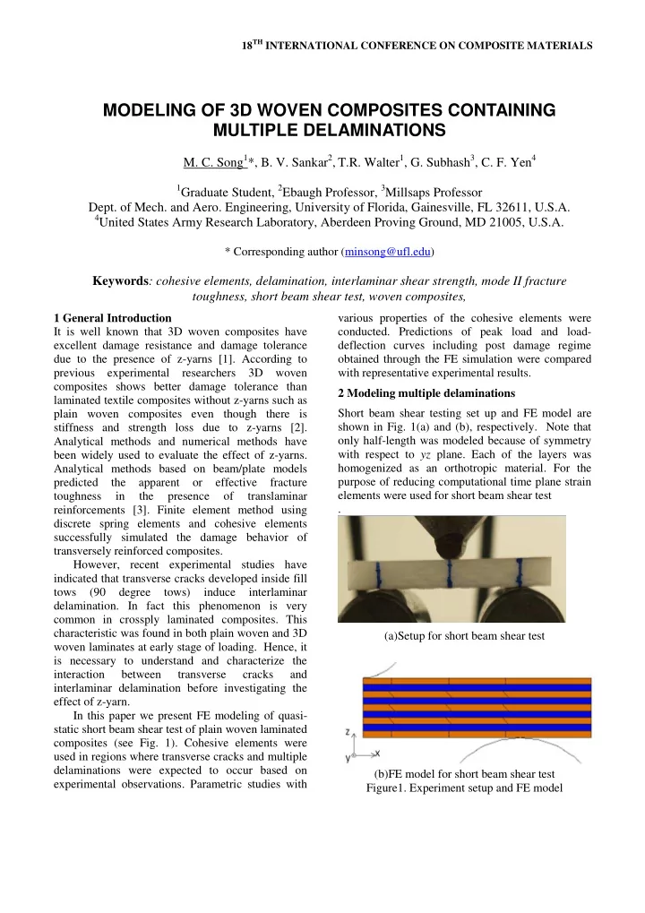
with representative experimental results. 2 Modeling multiple delaminations Short beam shear testing set up and FE model are shown in Fig. 1(a) and (b), respectively. Note that

  • nly half-length was modeled because of symmetry

with respect to yz plane. Each of the layers was homogenized as an orthotropic material. For the purpose of reducing computational time plane strain elements were used for short beam shear test . (a)Setup for short beam shear test (b)FE model for short beam shear test

  • Figure1. Experiment setup and FE model

MODELING OF 3D WOVEN COMPOSITES CONTAINING MULTIPLE DELAMINATIONS

  • M. C. Song1*, B. V. Sankar2, T.R. Walter1, G. Subhash3, C. F. Yen4

1Graduate Student, 2Ebaugh Professor, 3Millsaps Professor

  • Dept. of Mech. and Aero. Engineering, University of Florida, Gainesville, FL 32611, U.S.A.

4United States Army Research Laboratory, Aberdeen Proving Ground, MD 21005, U.S.A.

* Corresponding author (minsong@ufl.edu)

Keywords: cohesive elements, delamination, interlaminar shear strength, mode II fracture toughness, short beam shear test, woven composites,

slide-2
SLIDE 2

The specimen used for this study was a plain woven laminated composite stacked in

(0 /45 ) /0 2 pw pw pw S

  • sequence. Superscript of pw

denotes plain woven. Each of layers consists of S-2 glass fibers and SC-15 epoxy matrix. Material properties for 0 degree plain woven were obtained from the previous research of Xiao et al [4]. These properties are shown in table 1. Table 1. Elastic properties for plain woven composites

E1=E2 E3 G13=G23 G12

13= 23 12

(Mpa) (Mpa) (Mpa) (Mpa) 27.5 11.8 2.14 2.9 0.4 0.11

The properties for 45-degree plain woven layer could be obtained using appropriate coordinate

  • transformation. In order to model intralaminar

failure (transverse cracks) and interlaminar failure (delamination) cohesive elements associated with damage functions were employed. The cohesive elements were placed between layers and the center

  • f fill tows for interlaminar delamination and

transverce cracks, respectively. These locations were based on experimental observations where most transverse cracks appeared within fill tows (90 degree fiber direction). Since warp tows and fill tows comprising woven composites are unidirectional fiber composites, this observation does not violate a general rule that transverse tensile strength of unidirectional composites is less than that

  • f matrix. And it is reasonable to assume that

transverse cracks form at the center of fill tows since specific location inside the fill tows have no significant difference in global deformation. It was assumed that direction of pre-defined crack paths at top and bottom layers were in the transverse direction (perpendicular to the longitudinal direction

  • f the beam) while crack paths at other layers were

at 45-degree to the longitudinal direction. This was based on the principal stress direction as depicted in

  • Fig. 1(b).

The use of cohesive element associated of damage function makes it possible to demonstrate progressive delamination. One of the key issues is define the parameter for damage function of cohesive elements. Traction separation law has been used for damage function for cohesive element. Bi- linear cohesive model was adopted for current study. This function enables stiffness loss to be calculated as delamination propagates.

(1 ) , , 1 ,

f f f f

D Kd d d d d d D d d d d d d d d

(1) where is traction, K is stiffness, D is damage variable, d is displacement, d0 is displacement at damage initiation and df is final displacement . Quadratic stress based failure criterion was used for damage initiation for both transverse crack and interlaminar delamination.

2 2

1

n s

  • n

s

(2) where

  • n and
  • s are interfacial normal and shear

strength.

Figure 2. Bi-linear damage curve for cohesive element

Table 2. Properties for cohesive elements

K

(N/mm3)

  • n

(Mpa)

  • s

(Mpa)

IC

G

(N/mm)

IIC

G

(N/mm) Transverse crack 106 50 70 1 3.8 Interlaminar delamination 106 30 40 1 3.8

In addition, quadratic relationship was used for damage propagation under mixed mode of normal and shear directions.

slide-3
SLIDE 3

3 MODELING OF 3D WOVEN COMPOSITES CONTAINING MULTIPLE DELAMINATIONS

2 2

1

I II IC IIC

G G G G

(3) The results from FE model are shown in Figs. 3 and

  • 4. From Fig. 3 one can note that the presence of

transverse cracks ensures delamination initiation consistent with the experimental observations. Load- deflection curve shown in Fig. 4 is helpful in understanding how local damage patterns affect the global deformation behavior of SBS specimens.

Figure 3. Comparison of damage patterns

Figure 4. Comparison of load-deflection curve Transverse crack due to tensile stress at bottom layer at early stage of loading cause stiffness loss. Other transverse cracks developed in middle layers result in interlaminar delamination. Once interlaminar delamination occurs, load begins to decrease. With more deflection, transverse crack and interlaminar delamination continue to develop. 3 Parametric studies 3.1 The effect of Mode II fracture toughness Parametric studies were performed for the sake of investigating the effect of inplane strength and interlaminar strength and fracture toughness on global behavior. By varying the cohesive parameters for transverse crack and interlaminar delamination, it is possible to demonstrate the effect of variation of strength and fracture toughness. To begin with, the variation of Mode II interlaminar fracture toughness values (3.4 N/mm, 3.8 N/mm and 4.2 N/mm) was considered since Mode II fracture is dominant under short beam shear loading. Material properties other than Mode II interlaminar fracture toughness were kept constant. Figure 5 shows the results for various Mode II fracture toughness values. It is seen that Mode II fracture toughness plays an important role in the post damage regime. Figure 5. Comparison of load-deflection curve for various interlaminar fracture toughnesses Lines from the origin to the point corresponding to a deflection of 2 mm were plotted to estimate the residual stiffness of specimens. Higher values of Mode II fracture toughness lead to higher residual stiffness and hence higher damage tolerance. 3.2 The effect of interlaminar shear strength Interlaminar shear strength is another important

  • parameter. Three values of interlaminar shear

strength,38, 40 and 42 MPa, were considered in this

slide-4
SLIDE 4
  • study. The results for various strengths are shown in
  • Fig. 6. As expected, higher value of interlaminar

shear strength resulted in higher peak load and lower residual stiffness. Figure 6. Comparison of load-deflection curve for various interlaminar shear strengths 3.3 The effect of transverse crack strength The global behavior of plain woven laminated composite is affected by interlaminar delaminations which are induced by transverse cracks. So it is necessary to investigate the variation of transverse crack strength. In this study, normal and shear strengths were changed in the same ratio with respect to the original values. Referring to Fig. 7, stiffness drops are delayed and residual stiffness tends to increase as transverse crack strengths

  • increases. However, peak loads are still controlled

by interlaminar shear strength. Strong tows prevent intralaminar cracks and delay delamination initiation and thus can increase damage tolerance. Figure 7. Comparison of load-deflection curve for various transverse crack strengths 4 Future work Three-dimensional woven composites can be used for enhanced damage tolerance. In order to understand the effect of z-yarn on delamination, simulation of short beam shear tests of 3D woven composites with 10% z-yarn will be performed. In the simulation, the properties for cohesive elements estimated from baseline specimen and discrete beam

  • r spring element to model z-yarns will be used. The

results from simulation will be analyzed in conjunction with experimental results. Fig.2. 10 % z-yarn woven composite [2]

  • 5. Summary

This paper focused on the simulation of short beam shear tests on plain woven laminates. FE model which includes transverse cracks and interlaminar delamination shows good agreement with experimental

  • bservations.

Parametric studies showed high values of interlaminar shear strength caused high peak loads, and increase of Mode II interlaminar fracture toughness resulted in increased damage tolerance. Acknowledgements The funding for this work was provided by the United States Army Research Office (grant number W911NF-08-1-0120), with Dr. Bruce LaMattina as the Program Manager and the United States Army Research Laboratory. The authors are grateful for the financial support. References

[1] S. K. Sharma and B. V. Sankar “Effects of Through-the-Thickness Stitching on Impact and Interlaminar Fracture Properties of Textile

slide-5
SLIDE 5

5 MODELING OF 3D WOVEN COMPOSITES CONTAINING MULTIPLE DELAMINATIONS Graphite/Epoxy Laminates.” NASA CR- 195042, 1995 [2] T. R. Walter, G. Subhash, B. V. Sankar and C. F. Yen “Monotonic and cyclic short beam shear response of 3D woven composites”. Composite Science and Technology, Vol. 70, pp 2190-2197, 2010. [3] M. C. Song, B. V. Sankar, G. Subhash and C. F. Yen "An Analytical Non-Dimensional Model for Mode I Delamination

  • f

Z-Pinned Composites,”25th Annual Technical Conference

  • f the American Society of Composites, CD

ROM Proceedings, Dayton, Ohio, September 2010 [4] J. R. Xiao, B. A. Gama, J. W. Gillespie Jr “Progressive and delamination delamination in plain weave S-2 glass/SC-15 composites under quasi-static punch-shear loading”, Composite structures, Vol 78, pp 182-196, 2007 [5] M. Tanoglu, S. Robert, D. Heider, S.H. McKnight, V. Brachos, J.W. Gillespie Jr.” Effects of thermoplastic preforming binder on the properties of S2-glass fabric reinforced epoxy composites”, International Journl of Adhesion and Adhseives, Vol 21, pp 187-195, 2001