Modeling Objects A prototype has a default size, position, and - - PowerPoint PPT Presentation

modeling objects
SMART_READER_LITE
LIVE PREVIEW

Modeling Objects A prototype has a default size, position, and - - PowerPoint PPT Presentation

Modeling Objects A prototype has a default size, position, and Modeling orientation You need to perform modeling transformations to position it within the scene Hierarchical Transformations myCube() - Create a unit cube with its origin


slide-1
SLIDE 1

Modeling

Hierarchical Transformations Hierarchical Models Scene Graphs

Modeling Objects

A prototype has a default size, position, and

  • rientation

You need to perform modeling transformations to

position it within the scene

myCube() - Create a unit cube with its origin at (0,0,0) To create a 2 x 0.1 x 2 table top - need to call glScalef(2, 0.1, 2)

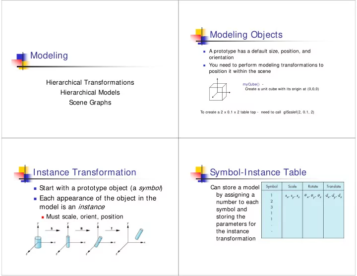
Instance Transformation

Start with a prototype object (a symbol) Each appearance of the object in the

model is an instance

Must scale, orient, position Defines instance transformation

Symbol-Instance Table

Can store a model by assigning a number to each symbol and storing the parameters for the instance transformation

slide-2
SLIDE 2

Symbol-instance table does not show

relationships between parts of model

Consider model of car

Chassis + 4 identical wheels Two symbols

Rate of forward motion determined by

rotational speed of wheels

Relationships in Car Model Structure Through Function Calls

car(speed) { chassis() wheel(right_front); wheel(left_front); wheel(right_rear); wheel(left_rear); }

  • Fails to show relationships well
  • Look at problem using a graph

Graphs

Set of nodes and edges (links) Edge connects a pair of nodes

Directed or undirected

Cycle: directed path that is a loop

loop

Tree

Graph in which each node (except the

root) has exactly one parent node

May have multiple children Leaf or terminal node: no children

root node leaf node

slide-3
SLIDE 3

Tree Model of Car DAG Model

If we use the fact that

all the wheels are identical, we get a directed acyclic graph

Not much different

than dealing with a tree

Modeling with Trees

Must decide what information to place

in nodes and what to put in edges

Nodes

What to draw Pointers to children

Edges

May have information on incremental

changes to transformation matrices (can also store in nodes)

Robot Arm

robot arm parts in their own coordinate systems

slide-4
SLIDE 4

Articulated Models

Robot arm is an example of an

articulated model

Parts connected at joints Can specify state of model by

giving all joint angles

Relationships in Robot Arm

Base rotates independently

Single angle determines position

Lower arm attached to base

Its position depends on rotation

  • f base

Must also translate relative

to base and rotate about connecting joint

Relationships in Robot Arm

Upper arm attached to

lower arm

Its position depends on

both base and lower arm

Must translate relative to

lower arm and rotate about joint connecting to lower arm

Required Matrices

Rotation of base: Rb

Apply M = Rb to base

Translate lower arm relative to base: Tla Rotate lower arm around joint: Rla

Apply M = Rb Tla Rla to lower arm

Translate upper arm relative to upper arm:

Tua

Rotate upper arm around joint: Rua

Apply M = Rb Tla Rla Tua Rua to upper arm

slide-5
SLIDE 5

OpenGL Code for Robot

robot_arm() { glRotate(theta, 0.0, 1.0, 0.0); base(); glTranslate(0.0, h1, 0.0); glRotate(phi, 0.0, 1.0, 0.0); lower_arm(); glTranslate(0.0, h2, 0.0); glRotate(psi, 0.0, 1.0, 0.0); upper_arm(); }

Tree Model of Robot

Note code shows relationships between

parts of model

Can change “look” of parts

easily without altering relationships

Simple example of tree model Want a general node structure

for nodes

Scene Graphs

Encoding this information in the code is

not very productive. Want it to be flexible, data-driven and extensible.

Scene-graphs provide this functionality.

OpenInventor (http://www.coin3d.org/) Open Scene Graph (http://www.openscenegraph.com/) Many others

Hierarchical Modeling

Triangles, parametric curves and

surfaces are the building blocks from which more complex real- world objects are modeled.

Hierarchical modeling creates

complex real-world objects by combining simple primitive shapes into more complex aggregate objects.

slide-6
SLIDE 6

Articulated Models Multiple Components

Different Materials

Scene Layout – Worlds

Hierarchical models

slide-7
SLIDE 7

Hierarchical models Hierarchical models Hierarchical models Hierarchical models

slide-8
SLIDE 8

Hierarchical Grouping of Objects

Logical organization of scene chair table fruits ground

Simple Example with Groups

Group { numObjects 3 Group { numObjects 3 Box { <BOX PARAMS> } Box { <BOX PARAMS> } Box { <BOX PARAMS> } } Group { numObjects 2 Group { Box { <BOX PARAMS> } Box { <BOX PARAMS> } Box { <BOX PARAMS> } } Group { Box { <BOX PARAMS> } Sphere { <SPHERE PARAMS> } Sphere { <SPHERE PARAMS> } } } Plane { <PLANE PARAMS> } }

Adding Materials

Group { numObjects 3 Material { <BLUE> } Group { numObjects 3 Box { <BOX PARAMS> } Box { <BOX PARAMS> } Box { <BOX PARAMS> } } Group { numObjects 2 Material { <BROWN> } Group { Box { <BOX PARAMS> } Box { <BOX PARAMS> } Box { <BOX PARAMS> } } Group { Material { <GREEN> } Box { <BOX PARAMS> } Material { <RED> } Sphere { <SPHERE PARAMS> } Material { <ORANGE> } Sphere { <SPHERE PARAMS> } } } Material { <BLACK> } Plane { <PLANE PARAMS> } }

Adding Transformations

slide-9
SLIDE 9

Hierarchical Transformation of Objects

Transforms position

logical groupings of

  • bjects within the

scene

Simple Example with Transforms

Group { numObjects 3 Transform { ZRotate { 45 } Group { numObjects 3 Box { <BOX PARAMS> } Box { <BOX PARAMS> } Box { <BOX PARAMS> } } } Transform { Translate { -2 0 0 } Group { numObjects 2 Group { Box { <BOX PARAMS> } Box { <BOX PARAMS> } Box { <BOX PARAMS> } } Group { Box { <BOX PARAMS> } Sphere { <SPHERE PARAMS> } Sphere { <SPHERE PARAMS> } } } } Plane { <PLANE PARAMS> } }

Separating types of transformation

Note that we have treated translations,

rotations, etc. as separate

But they are all represented by 4x4 matrices

and there is no technical reason not to combine them into the resulting matrix

It’s just simpler for the human programmer,

and corresponds to the handle of 3D modeling/animation packages

Hierarchical modeling in OpenGL

Commands to change current transformation

glTranslate, glScale, etc.

Affects the state, i.e. all following commands

will undergo this transformation

Utilities to maintain a matrix stack (to revert

to previous state)

Difference between model and view matrix

slide-10
SLIDE 10

Model vs. Projection matrix

  • It is almost the same to rotate the camera or the objects
  • Main difference:
  • Lighting
  • This is why OpenGL has two transforms: model and projection

glMatrixMode( GL_MODELVIEW );

  • Tells openGL that next matrix commands deal with the objects.
  • typically used for modeling & animation

glMatrixMode(GL_PROJECTION);

  • Tells OpenGL we deal with the camera space (
  • typically used to change viewpoint & focal length

Managing the state

To reset everything:

glLoadI dentity();

OpenGL stores a

stack of matrices

You don’t need to

remember, OpenGL remembers

glPushMatrix() glPopMatrix

Managing the state

Push matrix when

you start rendering a group

Pop once you are

done

Scene Graph

Convenient Data structure for scene

representation

Transformations Materials, color Multiple instances

Basic idea: Hierarchical Tree Useful for manipulation/animation

Especially for articulated figures

Useful for rendering too

Multi-pass rendering, occlusion culling

slide-11
SLIDE 11

Scene Graphs

Basic idea: Tree Comprised of several node

types:

Shape: 3D geometric objects Transform:

Affect current transformation

Property: Appearance, texture,

etc.

Group: Collection of subgraphs

Traversal

Depth first

Top to bottom, left to right

Traversal State

The State is updated during traversal

Transformations, properties Influence of nodes can be complex E.g. bottom to top

Other Scene Nodes

Switch or Selector Nodes

Level of detail Different rendering styles Damaged v. undamaged states

Sequence Nodes

Animated sequence

Objects Textures Transformations

slide-12
SLIDE 12

Object Following or Tethering

Can attach an object to the node of

another object (or group them in a parent node.

Provide an offset to have the other

  • bject tag along with the object under

control.

Camera Tethering

Many times, we want the camera to follow

an entity.

Need to get the coordinate frame for the

entity.

Traverse the scene graph to the entity.

Or, need to get the current camera system

Attach camera and determine transformations

to the root of the scene graph.