
SLIDE 1
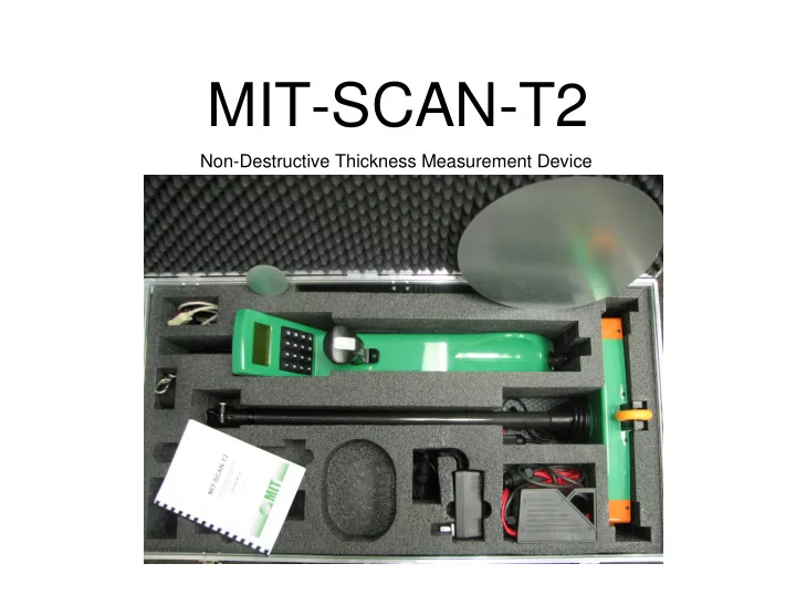
MIT-SCAN-T2
Non-Destructive Thickness Measurement Device
MIT-SCAN-T2 Non-Destructive Thickness Measurement Device INSTRUMENT - - PowerPoint PPT Presentation
MIT-SCAN-T2 Non-Destructive Thickness Measurement Device INSTRUMENT CAPABILITIES Can measure to a depth of 460 mm (18 inches) Accuracy: [(0.5% of measured value in mm) + 1 mm] 3.3 mm for 460 mm (18 inches) thick pavement
Non-Destructive Thickness Measurement Device
Can measure to a depth of 460 mm (18 inches) Accuracy: ±[(0.5% of measured value in mm) + 1 mm] ±3.3 mm for 460 mm (18 inches) thick pavement Battery life: 8 Hrs. or 1,000 measurements Charging time: Zero to Full in 1.5 Hrs. Instrument weight with battery: 3 Kg (6.7 lb)
Magnetic Imaging Tomography Device generates magnetic field 4 sensors detect alterations caused by nearby metal objects Magnetic reflectors are placed on base layer prior to placement of PCCP
Zinc clad steel discs used as magnetic reflectors Selection based on designed layer thickness
Diameter: 70 mm Thickness: 0.6 mm Disc B: Diameter: 300 mm Thickness: 0.6 mm
Reflector disc Other reflector discs, dowel bars, keys, coins at least 0.5 m (1.6 ft) away Moving traffic, safety features at least 1 m (3.3 ft) away Parked cars at least 2 m (6.6 ft) away Construction equipment, heavy machinery at least 4 m (6.6 ft) away
JPCP Slab with Dowel and Tie bars
~ 915 mm (3 ft)
Proposed concrete slab 12 ft x 12 ft Place reflector disc in shaded area. Recommended placement area is lightly shaded Dowel bars Tie bars
~ 915 mm (3 ft)
Identify reflector disc type and placement location Place and secure reflector disc to base using PK nails or other fastening method
Base Subgrade Concrete slab
Ensure proper clearance from metal objects Power up MIT-SCAN-T2; select appropriate configuration file. Place MIT-SCAN-T2 about 300 mm (1 ft) in front of reflector disc Roll over reflector disc at slow and steady pace until beep sounds
Layer thickness is immediately displayed on screen in SI units ScanT software can be used to retrieve stored data from MIT-SCAN-T2 onto a computer in text format. The text file generated by ScanT can be imported into MS Excel