mincut placement
play

Mincut Placement Perform quadrature mincut onto 4 4 grid Start - PowerPoint PPT Presentation

Mincut Placement Perform quadrature mincut onto 4 4 grid Start with vertical cut first undirected graph model w/ k-clique weighting thin edges = weight 0.5, thick edges = weight 1 Practical Problems in VLSI Physical Design Mincut


  1. Mincut Placement � Perform quadrature mincut onto 4 × 4 grid � Start with vertical cut first undirected graph model w/ k-clique weighting thin edges = weight 0.5, thick edges = weight 1 Practical Problems in VLSI Physical Design Mincut Placement (1/12)
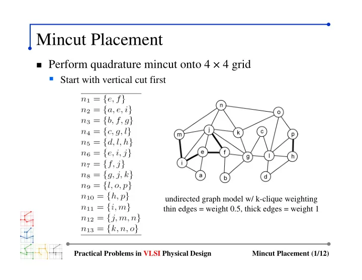
  2. Cut 1 and 2 � First cut has min-cutsize of 3 (not unique) � Both cuts 1 and 2 divide the entire chip Practical Problems in VLSI Physical Design Mincut Placement (2/12)

  3. Cut 3 and 4 � Each cut minimizes cutsize � Helps reduce overall wirelength Practical Problems in VLSI Physical Design Mincut Placement (3/12)

  4. Cut 5 and 6 � 16 partitions generated by 6 cuts � HPBB wirelength = 27 Practical Problems in VLSI Physical Design Mincut Placement (4/12)

  5. Recursive Bisection � Start with vertical cut � Perform terminal propagation with middle third window Practical Problems in VLSI Physical Design Mincut Placement (5/12)

  6. Cut 3: Terminal Propagation � Two terminals are propagated and are “pulling” nodes � Node k and o connect to n and j : p 1 propagated (outside window) � Node g connect to j, f and b : p 2 propagated (outside window) � Terminal p 1 pulls k / o / g to top partition, and p 2 pulls g to bottom Practical Problems in VLSI Physical Design Mincut Placement (6/12)

  7. Cut 4: Terminal Propagation � One terminal propagated � Node n and j connect to o / k / g : p 1 propagated � Node i and j connect to e / f / a : no propagation (inside window) � Terminal p 1 pulls n and j to right partition Practical Problems in VLSI Physical Design Mincut Placement (7/12)

  8. Cut 5: Terminal Propagation � Three terminals propagated � Node i propagated to p 1 , j to p 2 , and g to p 3 � Terminal p 1 pulls e and a to left partition � Terminal p 2 and p 3 pull f / b / e to right partition Practical Problems in VLSI Physical Design Mincut Placement (8/12)

  9. Cut 6: Terminal Propagation � One terminal propagated � Node n and j are propagated to p 1 � Terminal p 1 pulls o and k to left partition Practical Problems in VLSI Physical Design Mincut Placement (9/12)

  10. Cut 7: Terminal Propagation � Three terminals propagated � Node j / f / b propagated to p 1 , o / k to p 2 , and h / p to p 3 � Terminal p 1 and p 2 pull g and l to left partition � Terminal p 3 pull l and d to right partition Practical Problems in VLSI Physical Design Mincut Placement (10/12)

  11. Cut 8 to 15 � 16 partitions generated by 15 cuts � HPBB wirelength = 23 Practical Problems in VLSI Physical Design Mincut Placement (11/12)

  12. Comparison � Quadrature vs recursive bisection + terminal propagation � Number of cuts: 6 vs 15 � Wirelength: 27 vs 23 Practical Problems in VLSI Physical Design Mincut Placement (12/12)

Download Presentation
Download Policy: The content available on the website is offered to you 'AS IS' for your personal information and use only. It cannot be commercialized, licensed, or distributed on other websites without prior consent from the author. To download a presentation, simply click this link. If you encounter any difficulties during the download process, it's possible that the publisher has removed the file from their server.

Recommend


More recommend