
SLIDE 1
1 Fall 2008, MIMD
MIMD Overview
- MIMDs in the 1980s and 1990s
Distributed-memory multicomputers
Intel Paragon XP/S Thinking Machines CM-5 IBM SP2
Distributed-memory multicomputers with
hardware to look like shared-memory
nCUBE 3 Kendall Square Research KSR1
NUMA shared-memory multiprocessors
Cray T3D Convex Exemplar SPP-1000 Silicon Graphics POWER & Origin
General characteristics 100s of powerful commercial RISC PEs Wide variation in PE interconnect network
- Broadcast / reduction / synch network
2 Fall 2008, MIMD
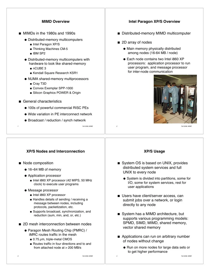
Intel Paragon XP/S Overview
- Distributed-memory MIMD multicomputer
2D array of nodes Main memory physically distributed
among nodes (16-64 MB / node)
Each node contains two Intel i860 XP
processors: application processor to run user program, and message processor for inter-node communication
3 Fall 2008, MIMD
XP/S Nodes and Interconnection
- Node composition
16–64 MB of memory Application processor
Intel i860 XP processor (42 MIPS, 50 MHz
clock) to execute user programs
Message processor
Intel i860 XP processor Handles details of sending / receiving a
message between nodes, including protocols, packetization, etc.
Supports broadcast, synchronization, and
reduction (sum, min, and, or, etc.)
2D mesh interconnection between nodes Paragon Mesh Routing Chip (PMRC) /
iMRC routes traffic in the mesh
0.75 µm, triple-metal CMOS Routes traffic in four directions and to and
from attached node at > 200 MB/s
4 Fall 2008, MIMD
XP/S Usage
- System OS is based on UNIX, provides
distributed system services and full UNIX to every node
System is divided into partitions, some for
I/O, some for system services, rest for user applications
Users have client/server access, can
submit jobs over a network, or login directly to any node
System has a MIMD architecture, but
supports various programming models: SPMD, SIMD, MIMD, shared memory, vector shared memory
Applications can run on arbitrary number
- f nodes without change