Microsystems D i g i t i z i n g Yo u r W o r l d S e a m l e s s l - - PowerPoint PPT Presentation

microsystems
SMART_READER_LITE
LIVE PREVIEW

Microsystems D i g i t i z i n g Yo u r W o r l d S e a m l e s s l - - PowerPoint PPT Presentation

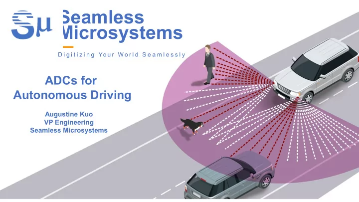
Seamless Microsystems D i g i t i z i n g Yo u r W o r l d S e a m l e s s l y ADCs for Autonomous Driving Augustine Kuo VP Engineering Seamless Microsystems Seamless Microsystems Background LiDAR and RADAR in Wireless and Consumer cars


slide-1
SLIDE 1

Seamless Microsystems

D i g i t i z i n g Yo u r W o r l d S e a m l e s s l y

Augustine Kuo VP Engineering Seamless Microsystems

ADCs for Autonomous Driving

slide-2
SLIDE 2

Seamless Microsystems Background

Consumer Medical Imaging Wireless and Wireline Comm.

SM250M SM250M SM250M SM400M

LiDAR and RADAR in cars

2

slide-3
SLIDE 3

3

Silicon Valley Traffic

slide-4
SLIDE 4

4

Tesla Autopilot! Available now!

slide-5
SLIDE 5

5

Works most of the time, but…

slide-6
SLIDE 6

6

Why Tesla’s autopilot might be failing?

Tesla’s autopilot only uses cameras and radar for sensing High resolution RADAR LiDAR

15 feet? 17 feet

slide-7
SLIDE 7

Sensor RADAR Camera/Vision LIDAR

Range Range resolution Angular resolution Works in bad weather Works in dark Works in bright light Radial velocity Color/contrast 7

Comparison of sensors in various environments

slide-8
SLIDE 8

8

Most autonomous cars now use all three sensors

LiDAR Camera RADAR

(usually mounted behind body panels)

slide-9
SLIDE 9

Laser PIN APD SPAD array A ADC Detection Estimation TDC Estimation 3-D Point Cloud 3-D Point Cloud Full waveform capture LiDAR Rx Geiger/Single-Photon LiDAR Rx OPTICAL ANALOG DIGITAL

12Gb/s 300Mb/s

Time-of-Flight LiDAR Systems

9

slide-10
SLIDE 10

Comparison of LiDAR receiver techniques

10

LiDAR Receiver Technique Geiger Mode Full-Waveform Capture

Processing simplicity/power consumption Cost Range/Resolution Quick Object Classification (reflectance data) Multi-return echo detection (ie foliage, poles/wires) Error-free from other LiDARs (interference)

slide-11
SLIDE 11

Current LiDAR solutions use discrete chips

$1600 for ADCs alone (8 channels)

ADC ADC ADC ADC ADC ADC ADC ADC

Digital 11

slide-12
SLIDE 12

ADCs in LiDAR Are Bulky and Expensive

Very hard to build Large footprint

ADC ADC ADC ADC ADC ADC ADC ADC

Digital

Speed Resolution 0.9 GHz 10-bits Power/ch. 1W

12

slide-13
SLIDE 13

LiDAR Receive Pulse Digitization

13 ADC

RX Chain

Time domain Pulse + Noise Frequency domain

LiDAR Received Pulse

4ns

▪ Sampling speed > 0.5GHz ▪ Resolution > 10-bits

LiDAR ADC Requirements

Bandwidth > 250MHz LPF

slide-14
SLIDE 14

Problem 1: Power Hungry LPF

ADC LPF LiDAR Pulse

▪ Significant SNR degradation due to noise aliasing ▪ Requires expensive LPF to minimize noise aliasing

  • 8th order LPF
  • 4x AD8099 chips @ $14
  • 600mW

2.5 5 7.5 10 15

Frequency Hz

108

  • 40
  • 35
  • 30
  • 25
  • 20
  • 15
  • 10
  • 5

Amplitude dB

Nyquist Band Alias Band 1 Alias Band 2 Alias Band 3 Alias Band 4 Alias Band 5

Analog LPF

Power hungry (600mW/ch.) and expensive ($14/ch)

14

slide-15
SLIDE 15

Problem 2: Poor Jitter Tolerance

15 ADC LPF LiDAR Pulse CLOCK

▪ Very accurate clock source requirement for ADC sampling ▪ <300fs rms jitter requirement for LiDAR ADCs ▪ Expensive

  • On-board clock generators: TI LMK61A2-100M00SIAT ~ $7.00
  • On-chip (inside ADC) clock generators
  • Large Silicon area
  • Large cost
slide-16
SLIDE 16

▪ Switched-capacitor input interface is hard to drive

  • Needs power hungry buffer

▪ ADC input driver ~ 20% ADC power consumption

Problem 3: Power-Hungry ADC Input Driver

Logic VREF

SAR 1 SAR 2 SAR N

ADC

RX Chain

LPF 16

slide-17
SLIDE 17

Best ADCs for LiDAR: Continuous-time DS ADCs

17

▪ High speed sigma delta ADCs

  • Enabled by SMI’s patented technology

▪ Inherent over-sampling

  • No requirement for anti-alias filter

▪ Resistive input impedance

  • Low power ADC driver

▪ Low-pass filtering using integrators before sampling ▪ Simple digital calibration

ò ò ò

SM 4-bit SM ADC 4-bit SCDAC Merged SMOA-RC Integrator-ADC

  • VIN

Calibration & Filtering

ANALOG DIGITAL DOUT

+ 12-bit

Seamless’ Continuous-Time DS ADCs

slide-18
SLIDE 18

18

ISO 26262 IP/Chip Requirements

All IP/SoCs must meet functional safety requirements

*Synopsys white paper – Data converters IP for Automotive SoCs

SMSP CT

SD ADC

+
  • IN
DOUT 12-bits 500MS/s FCLK = 3GHz SMSP CT

SD ADC

+
  • IN
DOUT 12-bits 500MS/s FCLK = 3GHz

SMSP CT

SD ADC

+
  • IN
DOUT 12-bits 500MS/s FCLK = 3GHz

SMSP CT

SD ADC

+
  • IN
DOUT 12-bits 500MS/s FCLK = 3GHz

SMSP CT

SD ADC

+
  • IN
DOUT 12-bits 500MS/s FCLK = 3GHz

SM250M 4 channel ADC With 1 redundant testing channel

slide-19
SLIDE 19

19 DIGITAL DIGITAL DIGITAL DIGITAL ADC ADC ADC ADC ADC

IP or Chiplets?

  • Digital will be a large portion of the

SoC

  • Done in lower CMOS nodes for

power/cost savings

  • ADCs as chiplets
  • Does not need to be in same

process as digital

  • Can be ISO 26262 qualified

independently to reduce time-to- market

slide-20
SLIDE 20

20

Conclusions

  • For autonomous driving sensors, high bandwidth and high

resolution ADCs will be needed

  • LiDAR/RADAR will definitely be used
  • Full-waveform capture needed for long range
  • Automotive components have long lead time
  • Products need to be done quickly so exhaustive tests can

begin sooner

  • ISO 26262 compliance is easier if every component is

already qualified