Memristor-The Missing Circuit Element LEON 0. CHUA, SENIOR MEMBER, - - PDF document

memristor the missing circuit element
SMART_READER_LITE
LIVE PREVIEW

Memristor-The Missing Circuit Element LEON 0. CHUA, SENIOR MEMBER, - - PDF document

507 NO. 5, SEPTEMBER 1971 ,EEE TRANSACTIONS ON CIRCUIT THEORY, VOL. CT-18, Memristor-The Missing Circuit Element LEON 0. CHUA, SENIOR MEMBER, IEEE Abstract-A new two-terminal circuit element-called the memrirtor- i(7J d7


slide-1
SLIDE 1 ,EEE TRANSACTIONS ON CIRCUIT THEORY, VOL. CT-18,
  • NO. 5, SEPTEMBER

1971 507

Memristor-The Missing Circuit Element

LEON 0. CHUA,

SENIOR MEMBER, IEEE

Abstract-A new two-terminal circuit element-called the memrirtor- characterized by a relationship between the charge q(t) s St% i(7J d7 and the

flux-linkage (p(t) = J-‘-m vfrj d

T is introduced
  • s the
fourth boric circuit element. An electromagnetic field interpretation
  • f
this relationship in terms
  • f
a quasi-static expansion
  • f
Maxwell’s equations is presented. Many circuit~theoretic properties
  • f
memdstorr are derived. It is shown that this element exhibiis some peculiar behavior different from that exhibited by resistors, inductors,
  • r
capacitors. These properties lead to a number
  • f
unique applications which cannot be realized with

RLC net-

works alone.

I + ”

  • 3

nl

Although a physical memristor device without internal power supply has not yet been discovered,
  • perational
laboratory models have been built with the help
  • f
active circuits. Experimental results
  • re
presented to demonstrate the properties and potential applications
  • f
memristors.

(a)

  • I. 1NTR00~cnoN

I + Y

  • 3

T

HIS PAPER presents the logical and scientific basis for the existence of a new two-terminal circuit element called the memristor (a contraction for memory (b) resistor) which has every right to be as basic as the three classical circuit elements already in existence, namely, the resistor, inductor, and capacitor. Although the existence

  • f a memristor in the form of a physical device without

internal power supply has not yet been discovered, its laboratory realization in the form of active circuits will be presented in Section II.’ Many interesting circuit-theoretic properties possessed by the memristor, the most important

  • f which is perhaps the passivity property which provides

the circuit-theoretic basis for its physical realizability, will be derived in Section III. An electromagnetic field in- terpretation

  • f the memristor characterization

will be pre- sented in Section IV with the help of a quasi-static expansion

  • f Maxwell’s
  • equations. Finally,

some novel applications

  • f memristors will be presented in Section V.

1 + ”

  • 3

I +

  • 3

  • (cl

Cd)

  • II. MEMRISTOR-THE

FOURTH BASIC CIRCUIT ELEMENT

From the circuit-theoretic point of view, the three basic two-terminal circuit elements are defined in terms of a relationship between two of the four fundamental circuit variables, namely;the current i, the voltage v, the charge q,

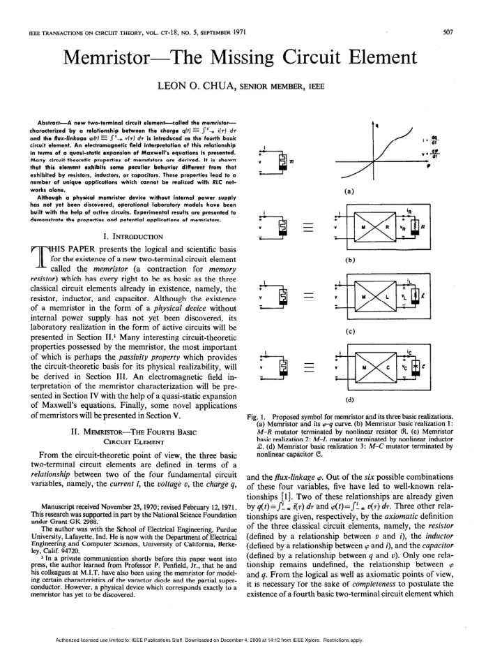
  • Fig. 1. Proposed symbol for memristor and its three basic realizations.

(a) Memristor and its q-q curve. (b) Memristor basic realization 1:

M-R mutator terminated by nonlinear resistor &t. (c) Memristor

basic realization 2: M-L mutator terminated by nonlinear inductor

  • C. (d) Memristor basic realization 3: M-C mutator terminated by

nonlinear capacitor e.

Manuscript

received November 25, 1970; revised February 12,197l. This research was supported in part by the National Science Foundation under Grant GK 2988. The author was with the School of Electrical Engineering, Purdue University, Lafayette, Ind. He is now with the Department of Electrical Engineering and Computer Sciences, University of California, Berke- ley, Calif. 94720. r In a private communication shortly before this paper went into press, the author learned from Professor P. Penfield, Jr., that he and his colleagues at M.I.T. have also been using the memristor for model- ing certain characteristics of the varactor diode and the partial super-

  • conductor. However, a physical device which corresponds exactly to a

memristor has yet to be discovered.

and theflux-linkage cp. Out of the six possible combinations

  • f these four variables, five have led to well-known

rela- tionships [l]. Two of these relationships are already given by q(t)=JL w i(T) d 7 and cp(t)=sf. m D(T)

  • d7. Three other rela-

tionships are given, respectively,. by the axiomatic definition

  • f the three classical circuit elements, namely, the resistor

(defined by a relationship between v and i), the inductor (defined by a relationship between cp and i), and the capacitor (defined by a relationship between q and v). Only one rela- tionship remains undefined, the relationship between 9 and q. From the logical as well as axiomatic points of view, it is necessary for the sake of completeness to postulate the existence of a fourth basic two-terminal circuit element which

Authorized licensed use limited to: IEEE Publications Staff. Downloaded on December 4, 2008 at 14:12 from IEEE Xplore. Restrictions apply.

slide-2
SLIDE 2

508

IEEE TRANSACTIONS ON CIRCUIT THEORY, SEPTEMBER 1971

TABLE I

CHARACTERIZATION AND REALIZATION OF M-R,

M-L,

AND M-C MUTATORS

=

‘PE I I
  • 2
I I
  • 2
I I 2
  • RANSMISSION
MATRIX ::I = [T(P’][J BASH: REALIZATIONS USING CONTROLLED SOURCES

SYMBOL AND

CHARACTERIZATION

’ : v

i : Y !I .I , '1 f)

REALIZATION 2 REALIZATION I ‘2

w+gf

+ R “2 il D---a + I c (2) + i2+ “2 (li,dt) il F--a- +(!%)
  • i2+
+ “2 Uqdt)
  • P
~R,b) = [ 1 P dVp “I= dt dip iI = -7 (q.Vl
  • RvR,iR)
Y-R MUTATOR REALIZATION I REALIZATION 2 di2 VI’
  • 7
REALIZATION 2 REALIZATION I gq-: Identical to TcR,(p) f c Type I C-R MUTATOR 1 REALIZATtON 4 REALIZATION 3 REALIZATION I “I = “2 di2 iI=-

!TDq-y I +(!!k) i2+ + (VI)- “!

M-L MUTATOR L 1 REALIZATION 2

(q,# -WL, iL) m

di, v, = - dt i, =v2 P TML2fP” )
  • [ 1
(Identical to TLR2(p) mf c Type 2 L-R MUTATOA REALIZATION 2 :f-pq* REALIZATlON I i, = - i2 P k,(P)
  • (

[ 1

(I&tical 10 TLRltp) d a Type I L-R MUTATOR l I ; REALlZATlON 3 REALIZATlON 4 M-C MUTATOR REALIZATION I v, =-i 2 d”2 il =r(t REALIZATION 2
  • r. ,-
il i2 + (ipI
  • D---a
“I ; + x t/ildt)- I

+ 3pq

“2

blcp= p

  • 1
(Idtmticdl t0 TCR2 ( p) ,f a Type 2 C-R WTATOF

Authorized licensed use limited to: IEEE Publications Staff. Downloaded on December 4, 2008 at 14:12 from IEEE Xplore. Restrictions apply.

slide-3
SLIDE 3 CHUA: MEMRISTOR-MISSING CIRCUIT ELEMENT

509

+Ecc

014 l?&l50) R4( IOOK) RJ9lO) (2~4236) L

I f I 1 1 h-b--&

4- 1 AR, 1 SO-IOA JRLq-

I I I ’ *-kc

k

  • +

1

“2
  • Port
2
  • Fig. 2. Practical active circuit realization of type-l M-R mutator based on realization 1 of Table I.

is characterized by a cp-q curve.2 This element will hence- forth be called the memristor because, as will be shown later, it behaves somewhat like a nonlinear resistor with memory. The proposed symbol of a memristor and a hypothetical cp-q curve are shown in Fig. l(a). Using a ,mutator [3], a memristor with any prescribed p-q curve can be realized by connecting an appropriate nonlinear resistor, inductor, or capacitor across port 2 of an M-R mutator, an M-L

mutator, and an M-C mutator, as shown in Fig. l(b), (c),

and (d), respectively. These mutators, of which there are two types of each, are defined and characterized in Table I.3 Hence, a type-l M-R mutator would transform the uR-if< curve of the nonlinear resistor f(u,+ iR)=O into the corre- sponding p-q curvef(cp, q)=O of a memristor. In contrast to this, a type-2 M-R mutator would transform the iR-vR curve of the nonlinear resistor f(iR, uR)=O into the corre- sponding p-q curvef(9, q) = 0 of a memristor. An analogous transformation is realized with an M-L mutator (M-C mutator) with respect to the ((PL, iL) or (iL, cp~) [(UC, qc) or (qc, UC)] curve of a nonlinear inductor (capacitor). Each of the mutators shown in Table I can be realized by a two-port active network containing either one or two controlled sources, as shown by the various realizations in Table 1. Since it is easier to synthesize a nonlinear resistor with a prescribed u-i curve [l], only operational models of k-R mutators have been built. A typical active circuit realizatian based on realization 1 (Table I) of a type-l M-R mutator is given in Fig. 2. In order to verify that a memristor is indeed realized across port 1 of an M-R muta- tor when a nonlinear resistor is connected across port 2, it

2 The postulation of new elements for the purpose of completeness

  • f a physical system is not without scientific precedent. Indeed, the

celebrated discovery of the periodic table for chemical elements by Mendeleeff in 1869 is a case in point [2]. 3 Observe that a type-l (type-2)‘M-L mutator is identical to a type-l (type-2) C-R mutator (L- R’mutator). Similarly, a type-l (type-2) M-C mutaror is identical to a type-l (type-2) L-R mutator (C-R mutator).

would be necessary to design a p-q curL;e tracer. The com- plete schematic diagram of a practical p-q curve tracer is shown in Fig. 3.4 Using this tracer, the p-q curves of three memristors realized by the type-l M-R mutator circuit of

  • Fig. 2 are shown in Fig. 4(b), (d), and (f) corresponding to

the nonlinear resistor V-Z curve shown in Fig. 4(c), (e), and (g), respectively. To demonstrate the rather “peculiar” voltage and current waveforms generated by the simple memristor circuit shown in Fig. 5(a), three representative memristors were synthesized with q--q curves as shown in Fig. 5(b), (d), and (f), respectively. The oscilloscope tracings of the voltage u(t) and current i(t) of each memristor are shown in Fig. 5(c), (e), and (g), respectively. The waveforms in

  • Fig. 5(c) and (e) are measured with a 63-Hz sinusoidal input

signal, while the waveforms shown in Fig. 5(g) are measured with a 63-Hz triangular input signal. It is interesting to ob- serve that these waveforms are rather peculiar in spite of the fact that the cp-q curve of the three memristors are relatively

  • smooth. It should not be surprising, therefore, for us to

find that the memristor possesses certain unique signal- processing properties not shared by any of the three existing classical elements. In fact, it is precisely these properties that have led us to believe that memristors will play an important role in circuit theory, especially in the area of device model- ing and unconventional signal-processing applications. Some

  • f these applications will be presented in Section V.

III. CIRCUIT-THEORETIC PROPERTIES OF MEMRISTORS

By definition a memristor is characterized by a relufiorz

  • f the type g(;p, q)=O. It is said to be charge-controlled

(flux-controlled) if this relation can be expressed as a single- valued function of the charge rZ (flux-linkage a). The voltage

4 For additional details concerning the design and operational char- acteristics of the circuits shown in Figs. 2 and 3, as well as that for a type-2 M-R mutator, see [4].

Authorized licensed use limited to: IEEE Publications Staff. Downloaded on December 4, 2008 at 14:12 from IEEE Xplore. Restrictions apply.

slide-4
SLIDE 4 IEEE TRANSACTIONS ON CIRCUIT THEORY, SEPTEMBER 1971

IAMETER SPECIFICAT0NS (current sensing

  • ruustor. i;p~cal

value: I, I), loo, or ooon ). qgbca* factor for mtegmtof, should be ot b+t 5K).

R12

. R,s (I K wtenttomelsr for

  • ffset adjustment for

LM202 OP AMP I. R~s ,R22 (trmwnmg ieststor for NEXUS SO-IOA OP AMP, typtool voluo: 20K).

cp .c3.cg

(nsutrollzotlon

  • capocltors. sea te*t 1

CT ( scale factor for Integrator, see tmt1. ( power supply voltag.e. * I5 Yolts rtth respect to qound).

I =

to l hwlZOontol

twmiml Of

  • uilloscop*

+ t

v,( t I= k, jvbldr
  • -(D

I to ground terminal d

  • scilbscom
  • .

+ to

‘sine v,(t) *IO”8 VoltogI gonratot

to + vwtlcd

r terminal of

L

  • scillo*copr

t vi{ t )*k, ]ilr)dr

  • k

ze!?-s X

%C5

I to ground

twmiml of

  • scilloscope
  • Fig. 3. Complete schematic diagram of memristor tracer for tracing the pq curve of a memristor.

Authorized licensed use limited to: IEEE Publications Staff. Downloaded on December 4, 2008 at 14:12 from IEEE Xplore. Restrictions apply.

slide-5
SLIDE 5

.

CHUA: MEMRISTOR-MISSING CIRCUIT ELEMENT

511

( bLH0nz0ntol Scole:lO-lweber per division. Vertical Scale: 2 ,L coul per division. (C l.Horizontol &ok: 2 volts per dwision. Vertlcol Scale: 2 ma per division. Vertical Scale: 5 c coul per ‘division. (e).Horizontol Scale: 2 volts per divsion. Vertical Scale: 4 ma per diviaan.

across a charge-controlled memristor is given by I I where Similarly, the current

  • f a flux-controlled

memristor is given by where

(4)

Since M(q) has the unit of resistance, it will henceforth be called the incremental memristance. In contrast to this, the function W(q) will henceforth be called the incremental menductance because it has the unit of a conductance. Observe that the, value of the incremental memristance (memductance) at any time to depends upon the time integral of the memristor current (voltage) from t = - co to t= to. Hence, while the memristor behaves like an ordi- nary resistor at a given instant of time to, its resistance (conductance) depends on the complete past history of the memristor current (voltage). This observation justifies our choice of the name memory resistor, or memristor. It is interesting to observe that once the memristor voltage u(t)

  • r current i(t) is specified, the memristor

behaves like a linear time-varying re@stor. Tn the very special case where the memristor vq curve is a straight line, we obtain M(q) = R,

  • r W(p)= G, and the memristor reduces to a linear time-

invariant resistor. Hence, there is no point introducing a linear memristor in linear network theory.5 We have already shown that memristors with almost any cp-q curve can be synthesized in practice by active networks. The following passivity criterion shows what class of mem- ristors might be discovered in a pure “device form” without internal power supplies. Theorem I: Passivity Criterion A memristor characterized by a differentiable charge- controlled p-q curve is passive if, and only if, its incremental memristance M(q) is nonnegative; i.e., M(q)>O. Proof: The instantaneous power dissipated by a memristor is given by PO) = W(Q = fifMO)b(O12.

(5)

Hence, if the incremental memristance M(q)>O, then p(t)>0 and the memristor is obviously passive. To prove the converse, suppose that there exists a point q. such that M(qo)<O. Then the differentiability

  • f the p-q curve implies

that there exists an e> 0 such that M(qo+ Aq)<O,

1Aq ( <e.

Now let us drive the memristor with a current i(t) which is zero for t<f and such that q(t)=qO+Aq(t) for t>_ to>? where 1

Aq( t) I< e

; then J! (o P(T) & < 0 for sufficiently large t, and hence the memristor is active. Q.E.D. We remark that the above criterion remains valid if the “differentiability” condition is replaced by a “continuity” condition, provided that the left- and right-hand derivative at each point on the cp-q curve exists. This criterion shows that only memristors characterized by a monotonically in- creasing p-q curve can exist in a device form without in- ternal power supplies. We also remark that except possibly for some pathological p-q curves,6 a passive memristor does not seem to violate any known physical laws.

5 Since research in circuit theory in the past has been dominated by linear networks, it is not surprising that the concept of a memristor never arose there. Neither is it surprising that this element is not even yet discovered in a device form because it is somewhat Yunnatural” to associate charge with flux-linkage. Moreover, the necessity to design

a qq curve tracer all but eliminates the slim possibility of an accidental

discovery. 6 It is possible for a passive circuit element to violate the second law

  • f thermodynamics. For a thought-provoking exposition on this topic,

see [5].

Authorized licensed use limited to: IEEE Publications Staff. Downloaded on December 4, 2008 at 14:12 from IEEE Xplore. Restrictions apply.

slide-6
SLIDE 6

512

IEEE TRANSACTIONS ON CIRCUIT THEORY, SEPTEMBER 1971

t

q.(t)

=ii(r)dr

  • m

(a ). Simple Memristor Voltage- Divider Circuit Q, milli- weber 1, msec. t , msec. ( c hlorizontol Scale: 2 msec. per division. Vertical Scale:5 mo per division (upper trace). lOvolts per division (lower trace). ( b 1 Horuontal Scole:2.66 milli-weber per division, Vertical Stole: 5 p coul per division. t , msec.

  • p. milli-

weber t, msec. (e LHorizontol Scale: 5 msec. per divisioo. Vertical Scale:2 mo per division (upper tmce).

5

volte per division (lower trace). (d Mlorizontol Scala: 2.66 milli-weber per division. Vertical Scale: 5 p coul per division. p, milli- weber ( f Mlorizontol Scale: 2.66 milli-weber per division, Vertical Scale: 5 p coul per division. (g ).Horizontol Scale:5 msec. per division. Vertical Scale:5 mo per division (upper trace). 5 wits per division (lower trace).

  • Fig. 5. Voltage and current waveforms associated with simple memristor circuit corresponding to a sinusoidal input

signal [(c) and (e)] and a triangular input signal r(g)], respectively.

Theorem 2: Closure Theorem A one-port

containing

  • nly memristors

is equivalent to a memristor.

Proof: If we let ii, vj, qj, and vj denote the current, voltage, charge, and flux-linkage

  • f the jth

memristor, where j= 1,

2;.., b, and if we let i and v denote the port current and port voltage of the one-port, then we can write (n- 1) inde- pendent KCL (Kirchhoff current law) equations (assuming the network is connected); namely,

CvjOi + 2 ajkik = 0,

j=l,2,.*.,n-1 (6)

k=l

where ajk is either 1, - 1, or 0, b is the total number of memristors, and n is the total number of nodes. Similarly, we can write a system of (b-n+2) independent KVL (Kirchhoff voltage law) equations:

@j&J + 5 PjkVk = 0,

j=l,2,..., b - n + 2 (7)

k=l

where @jk is either 1, - 1, or 0. If we integrate each equation in (6) and (7) with respect to time and then substitute ‘pk = (pk(qk) for pk in the resulting expressions,7 we obtain & ffjk@ = Qj - ffjoPt j=l,2,***,n-1 (8)

PjOCp + f: pjk(pk(qk) = *j, j = 1, 27 ’ ’ . , b - n + 2

(9)

kzl

7 We have assumed for simplicity that the mernristors are charge-

  • controlled. The proof can be easily modified to allow memristors char-

acterized by arbitrary e curves.

Authorized licensed use limited to: IEEE Publications Staff. Downloaded on December 4, 2008 at 14:12 from IEEE Xplore. Restrictions apply.

slide-7
SLIDE 7 CHUA: MEMRISTOR-MISSING CIRCUIT ELEMENT

where Qj and @j are arbitrary constants of integration. Equa- tions (8) and (9) together constitute a system of (b+ 1) inde- pendent nonlinear functional equations in (b+ 1) unknowns. Hence, solving for cp, we obtain a relation f(q, cp) = 0. Q.E.D. Theorem 3: Existence and Uniqueness Theorems Any network containing

  • nly memristors with positive

incremental memristances has one, and only one, solution. Proof: Since the governing equations of a network contain- ing only memristors are identical in form to the governing equations of a network containing only nonlinear resistors, the proof follows mututis mutandis the well-known proof given in [6], [7]. Q.E.D. It is sometimes easier and more instructive to analyze a single-element-type nonlinear network by finding the @a- tionary points of an associated scalar poteiltial function [8], [9]. We will now present an analogous development of this concept for a pure memristor network.9 Dejnition 1 We define the action (coaction) associated with a charge- controlled (flux-controlled) memristor to be the integral Consider now a pure memristor network N containing n nodes and b branches. Let 3 be a tree of N and d: its associ- ated cotree. Let us label the branches consecutively starting with the tree elements and define v=(cpl, cpZ, . . . ¶+a¶ )” 4 =(ql, q2, . . . , q#, qa=(‘pl, CPZ, + a, . ,, ‘P~-#, and g, = (qn,

qn+1, . . . , q#. It is well known that either ea or qe coristi-

tutes a complete set of variables in the sense that (e=O& and q = Btq,, where D and B are the fundamental cut-set matrix and the fundamental loop matrix, respectively [IO]. Dejnition 2 We define the ,total actitin a(qJ [total coaction &(&I associated with a network N containing charge-controlled (flux-controlled) memristors to be the scalar function /a(s,)= /I (10) where A = A(q) = 5 Aj(qj> = f: J ” pj(qj) &j

j=l j=l j=l j=lJ

and where o denotes the “composition”

  • peration.

*To simplify the hypothesis, we assume that all memristors are characterized by differentiable onto functiotls. 9 Several useful potential functions have been defined for the three classical circuit elements. They are the content and cocontent of a re- sistor [8], the magnetic energy and magnetic coenergy of an inductor [9], and the electric energy and electric coenergy of a capacitor 191.

Theorem 4: Principle bf Stationary Action (Coaction) A vector qJ: = Qd: (ea =$) is a solution of a network N containing

  • nly charge-controlled

(flux-controlled) mem- ristors if, and only if, it is a stationary point of the total action a(qJ [total coaction a(&] associated with N; i.e., the gradient of a(qa) (&(I&) evaluated at Q6: (@J is zero: a@(d/aq, (Q=Q~ = 0 ab?pee, lo,=*, = 0. (12) Proof: It suffices to prove the charge-controlled case since the flux-controlled case will then follow by duality. Taking the gradient of a(qe) afid applying the chain rule for dif- ferentiating composite functions, we obtain

513

= BaA(q)/dq IGB’s, = By? o (BW. (13) But the expression BP o (Btq,)=O since this is simply the set of KVL equations written in terms of C. Consequently, any vector 9, is a solution of N if, arid only if, it is a sta- tionary point of Ct(qJ. Q.E.D. Since the action and coaction of a memristor is a: poten- tial function, they can be used to derive frequency power formulas for memristors operating. ris frequency converters. We assume the memristor is operating in the steady state so that we can write the following variables in multiply-periodic Fourier series: v(t) = Re c [V&at] i(t) = Re c [I,eQal] v(t) = Re 5 [&ej@]

q(t) = Re 5

[Qaej@] LI

  • 2

and A(t)=Rez [A,ehJ] OL where V,>_jw,@, and ‘lol>_joUQo. Following identical pro- cedure and notation as given in [ll, ch. 31, we let wa denote the set of independent frequencies and make a small change in

6~$,=Li(~,t).

This perturbation induces a change in the action A(t) : (14) But sintie A(q) = J&(q) dq, we have 6A = ((p)(Sq)

=

[ Re F TY @at WC2 1

.[Re c 5 (ao,/aw,)ej~‘hM, 1 1

(15) ’ LI al Equating (14) and (15) and taking their time averages, we

  • btain the following Manley-Rowe-like

formula relating the reactive powers P,=+ Im (V,Z,*): ~[ac&/awa] [P&a = 0 . (16)

P

Authorized licensed use limited to: IEEE Publications Staff. Downloaded on December 4, 2008 at 14:12 from IEEE Xplore. Restrictions apply.

slide-8
SLIDE 8

514

IEEE TRANSACTIONS ON CIRCUIT THEORY, SEPTEMBER

1971 It is possible to derive a Page-Pantell-like inequality re- lating the realpowers of a passive memristor by making use

  • f the passivity criterion (&)(64)>0

(Theorem 1); namely,

L I

where Pa=3 Re ( VaZz) is the real power at frequency w,. Since the procedure for deriving (17) follows again mutatis mutandis that given by Penfield [ 111, it will not be given here to conserve space. An examination of (17) shows that gain proportional to the frequency squared is likely in a mem- ristor upconverter, but that severe loss is to be expected in a memristor mixer. It is also easy to show that converting efficiencies approaching 100 percent may be possible in a memristor harmonic generator. So far we have considered only pure memristor networks. Let us now consider the general case of a network containing resistors, inductors, capacitors, and memristors. The equa- tions of motion for this class of networks now take the form

  • f a system of m first-order nonlinear differential equations

in the normal form $=f(x, t) [l], where x is an mX 1 vector whose components are the state variables. The number m is called the “order of complexity”

  • f the network and is equal

to the maximum number of independent initial conditions that can be arbitrarily specified [I]. The following theorem shows how the order of complexity can be determined by inspection. Theorem 5: Order of Complexity Let N be a network containing resistors, inductors, capaci- tors, memristors, independent voltage sources, and inde- pendent current sources. Then the order of complexity m of N is given by

  • 1

(18)

where br. is the total number of inductors; bc is the total number of capacitors; b,ll is the total number of memristors; nnl is the number of independent loops containing

  • nly

memristors; /?CE is the number of independent loops con- taining only capacitors and voltage sources; nL.ll is the number of independent loops containing

  • nly inductors

and memristors; h,,r is the number of independent cut sets containing

  • nly memristors;

fiLJ is the number of inde- pendent cut sets containing

  • nly inductors

and current sources; ric.nr is the number of independent cut sets con- taining only capacitors and memristors. ProCf: It is well known that the order of complexity of an RLC network is given by m=(bL+bc)-IzCE-YiLJ [l]. It follows, therefore, from (l)-(4) that for an RLC-memristor network with n, = nLlll = i?,,, = i2c.1, =O, each niemristor introduces a new state variable and we have m=(b,,+bc state variables occurs whenever an independent loop con- sisting of elements corresponding to those specified in the definition of IZ.&~ and nLw is present in the network. [We as- sume the algebraic sum of charges around any loop (flux- linkages in any cut set) is zero.] Similarly, a constraint among the state variables occms whenever an independent cut set consisting of elements corresponding to those speci- fied in the definition of fiM and &CM is present in the network. Since each constraint removes one degree of freedom each time this situation occurs, the maximum order of complexity (bL+bc+bM) must be reduced by one. Q.E.D.

  • IV. AN ELECTROMAGNETIC INTERPRETATION

OF MEMRISTOR CHARACTERIZATION

It is well known that circuit theory is a limiting special casg of electromagnetic field theory. In particular, the char- acterization

  • f the three classical circuit elements can be

given an elegant electromagnetic interpretation in terms of the quasi-static expansion of Maxwell’s equations [12]. Our

  • bjective in this section is to give an analogous interpreta-

tion for the characterization

  • f memristors.

While this interpretation does not prove the physical realizability

  • f a

“memristor device” without internal power supply, it does suggest the strong plausiblity that such a device might some- day be discovqred. Let us begin by writing down Maxwell’s equations in differential form: 09) curl H = J + f8f where E and H are the electric and magnetic field intensity, D and B are the electric and magnetic flux density, and J is the current density. We will follow the approach presented in [ 121 by defining a “family time” r=at, where a is called the “time-rate parameter.” In terms of the new variable T, Maxwell’s equations become dB curl E = - Ly

  • a7

curl H = J + a! $

(21)

(?a where E, H, D, B, and J are functions of not only the posi- tion (x, y, z), but also of (Y and 7. If we were to expand these vector quantities as a formal power series in cy and substitute them into (21) and (22), we would obtain upon equating the coeficients of CP, the nth-order Maxwell’s equaiions, where n=O, 1, 2, ’ . . . Many electromagnetic phenomena and systems can be satisfactorily analyzed by using only the zero-order and first-

  • rder Maxwell’s equations; the corresponding solutions are

called quasi-staticfields. It has been shown that circuit theory belongs to the realm of quasi-static fields and can be studied with the help of the following Maxwell’s equations in quasi- r . +b,+i)--ncg-CiLJ. Observe next that a constraint among the static form 1121.

Authorized licensed use limited to: IEEE Publications Staff. Downloaded on December 4, 2008 at 14:12 from IEEE Xplore. Restrictions apply.

slide-9
SLIDE 9 CHUA: MEMRISTOR-MISSING CIRCUIT ELEMENT

515 Zero-Order Maxwell’s Equations curl EIJ = 0 curl Ho = Jo. First-Order Maxwell’s Equations where 3( .), (R( .), and a)( .) are one-to-one continuous func- tions from R3 onto R3. Under these assumptions, (26) and (23) (27) can be combined to give (24) curl HI = d(E1). (30) aBo cur1 E1 = - a, Observe that (30) does not contain any time derivative. (25) hence, under any specified boundary con,dition appropriate for the device, the first-order electric field E1 is related to aoo curl HI = J1 -I- -.

a7

the first-order magnetic field HI dy a functional relation ; cw namely The total quasi-static vector quantities are obtained by keep- ing oniy the first two terms of the formal pdwer series atid by setting CY= 1; namely, E-Eo+E1, H=H”+Hl, D=&+D1, B= Bo+ B1, J-Jo+

  • JI. The three classical circuit elements

have been identified as electromagnetic systems whose solu- tions correspond to certain combinations

  • f the zero-order

and first-order solutions of (23)<26). For example, a re- sistor has been identified to be an electromagnetic system whose first-order fields are negligible compared to its zero-

  • rder fields, so that its characterization

can be interpreted as an instantaneous (memoryless) relationship between the two zero-order fields Eo and HO. In contrast to this, an in- ductor has been identified to be an electromagnetic system where only the first-order magnetii: field is nedigible. In this case, the electromagnetic system can be interpreted as an inductor in series with a resistor. Similarly, a capacitor has been identified to be an electromagnetic system where

  • nly the first-order electric field is negligible. In this case,

the electromagnetic system can be interpreted as a capacitor in parallel with a resistor. The remaining case where both first-order fields are not negligible has been dismissed as having no c&responding situation in circuit theory [ 121. We will now offer the suggestion that this missing combination is precisely that which gives rise to the characterization

  • f a

memristor. In order to add more weight to the above interpretation, we will now show that under appropriate conditions the instantaneous value of the first-order electric flux density D1 [whose surface integral is proportional to the charge q(t)] is related to the instantaneous value of the first-order mag- netic flux density B1 [whose surface integral is proportional to the flux-linkage p(t)]. This would be the case if we postu- late the existence of a two-terminal device with the following two properties. 1) Both zero-order fields are negligible com- pared to the first-order fields; namely, E= E1, H=H1, D-D], B= BI, and J- JI. 2) The material from which the device is made is nonlinear. To be completely general, we will denote the nonlinear relationships bylo JI = dE1) (27) Bl = 63(Hd (28) Dl = LD(&) (29) EI = f(H,). (31) If we substitute (31) for E1 in (29) and then substitute the in- verse function of CR( .) from (28) into the resulting expres- sion, we obtain D1 = a, o f o [W(B1)] = g(B1). (32) Equation (32) specified the instantaneous (memoryless) relationship between DI and BI; it can be interpreted as the quasi-static representation of the electromagnetic field quan- tities of the memristor. To summarize, we offer the interpretation that the physi- cal mechanism characterizing a memristor device must come from the instantineous (memoryless) interaction between the first-order electric field and the first-order magnetic field

  • f some appropriately

fabricated device so that it possesses the two properties prescribed above. This interpretation implies that a physical memristor device is essentially an ac device, for otherwise, its associated dc electromagnetic fields will give rise to nonnegligible zero-order fields. This require- ment is consistent with the circuit-theoretic properties of the memristor, for a dc current source would give rise to an in- finite charge [q(t) --+oo as t+w ] and a dc voltage source would give rise to an infinite flux-linkage [cp(t)+w as t-w ]. This requirement is, of course, intuitively reasonable. After all, we do not connect a dc voltage source across an inductor. Nor do we connect a dc current source across a capacitor!

  • V. SOME NOVEL APPLICATIONS OF MEMRISTORS

The voltage and current waveforms of the simple mem- ristor circuit shown in Fig. 5 are rather peculiar and are certainly not typical of those normally

  • bserved in RLC
  • circuits. This observation

suggests that memristors might give rise to some novel applications outside those for RLC

  • circuits. Our objective in this section is to present a number
  • f interesting examples which might indicate the potential

usefulness of memristors.

  • A. Applications of Memristors to Device Modeling”

Although many unconventional devices have been in- vented in the last few years, the physical operating principles

  • f most of these devices have not yet been fully understood.

In order to analyze circuits containing these devices, a lo

In the case

  • f isotropic material.

(27)-(29) reduce

to J, = u(&)&, B1=~(NI)HI, and DI=@~)E,, where the coefficients u(.), p(.), and *I The author is grateful to one of the reviewers who pointed out

4’ ) are the nonlinear conductivity, nonlinear magnetic permeability, and

that a charge-controlled memristor has been used in the modeling of

nor&new dielectric permittioity of the material.

varactar diodes

[13], [14].

Authorized licensed use limited to: IEEE Publications Staff. Downloaded on December 4, 2008 at 14:12 from IEEE Xplore. Restrictions apply.

slide-10
SLIDE 10

516

1EEETRANSACTIONSON CIRCUITTHEORY,SEPTEMBER

1971

RI

i + + ”

i

T v*( t 1 i “0 Rz l-

IO). I v*( t ) I----'1

v,(t) I E,

  • --_

T

  • -----_______
  • l

(e).

  • Fig. 6. Output voltage waveform I;,
  • f simple memristor circuit

shown in (a) corresponding to a stepwise input voltage u,(t) of different amplitudes bears a striking resemblance to corresponding waveforms

  • f the same

circuit but with the memristor replaced by typical amorphous

  • vonic threshold

switch. realistic “circuit model” must first be fpund. We will now show that the memristor can be used to yodel the properties

  • f two recently discovered, but unrelated, devices.

Example 1: Modeling an Amorphous “Ovonic” Threshold Switch An amorphous “ovonic” threshold switch is a two-ter- minal device which uses’an amdrphous glass rather than the more common crystalline semiconductqr material used in most solid-state devices [ 15]-[17]. This device lias already attracted much international attention because of its poten- tial usefulness [18], [19]. To show that the memristor pro- vides a reasonable model for at least one type of the amor- phous devices, let us consider the memrjstor circuit shown in

  • Fig. 6(a), where the 9-q curve of the memristor is shown in
  • Fig. 6(b).12

From Theorem 5 we know the order of complex- ity of this circuit is equal to one. The state equation is given

12 This circuit is identical to the switching circuit described in [15], [16], but with an ovonic threshold device connected in place of the

  • memristor. As explained in [HI, [16], this circliit operates like a switch

in the sense that prior to the applicatidn of a square-wave pulse, thk

  • vonic switch behaves like a high resistance and is said to be operating

in the OFF state. After the pulse is applied, the ovonic switch remains in its OFF state until after some rime delay Td; thereupon it switches to a low resistance state. Since the circuit is essentially a voltage divider, the

  • utput voltage u,(f) will be high when the ovonic switch is operating in

its OFF state, and will be low when it is operating in its ON state.

by

dq/dt = u&V[RI + Rz + M(q)]. Since the variables are separable, the solution is readily found to be where

I h(q) = 6% + R& + u?(q) I

and cp = cp(q) represents the cp-q curve of the memristor shown in Fig. 6(b). Observe that h(q) is a strictly monotonically in- creasing function of q; hence, its inverse h-‘( .) always exists. The output voltage uo(t) is readily found to be given by

v,(t) = v,(t)

  • R,[dq(t)/dt].

(36) If we let us(t) be a square-wave pulse, as shown in Fig. 6(c), and let q(Q=O, where lo is the initial time, then the output waveforms uo(t) and i(t), corresponding to the memristor Fq curve shown in Fig. 6(b), can be derived from (34)-(36); they are shown in Fig. 6(d) and (e). These output waveforms are completely characterized’by the following parameters: El = [(Kz + &)/CM, + RI + Rd]E (37) Ez = [(MS + Rz)/(M, + RI + Rd]E (3% II = E/(Mz + RI + Rd (39) Iz = E/CM, + RI + Rz) (40) Td = [$ + (RI + RNo]/E (41) where MZ and M, represent the memristance corresponding to segments 2 bnd 3 of the memristor cp-q curve and where (R,, QO) is the coordinate of the breakpoint between these two segments. An examination of (4 1) shows that for a given p-q curve, the time delay Td decreases as the amplitude E pf the square-wave pulse in Fig. 6(c) increases. Hence, corre- sponding to the three square-wave pulses with amplitude E, E’, and E’! (E’<E<E”) shown in ‘Fig. 6(c) and (f), we

  • btain the waveforms for the output voltage uo(t) as shown

in Fig. 6(d), (g), and (h), respectively. A comparison be- tween these waveforms with the corresponding published waveforms for the ovonic threshold switch reveals a striking resemblince [15], [16]. The memristor with the (p-9 curve shown in Fig. 6(b) seems to simulate not only the exact shape of the stepwise waveforms, but also the attendant de- crease of the time delay with increasing values of E.13

I3 Since the author has been unable to obtain a sample of an ovonic threshold switch, the comparisons were made only with published

  • waveforms. It is not clear how well our present memristor model will

simulate the rate of decrease of the time delay with increasing values

  • f E. In any event, the qualitative agreement with published waveforms

is quite remarkable.

Authorized licensed use limited to: IEEE Publications Staff. Downloaded on December 4, 2008 at 14:12 from IEEE Xplore. Restrictions apply.

slide-11
SLIDE 11 CHUA: MEMRISTOR-MISSING CIRCUIT ELEMENT

517 A V,(l) E . .

  • _
  • - - - -

ä l : to (cl I

4 vow 1

Td * E* _

  • _ ..- _ _ - . __- - _ _ _ - _ _

_ -- - - - E, .--w-w--.

‘0

b. @o+QoRI E *I ( to+T,-o (dl

  • Fig. 7. Output waveform u,(f) for basic timing circuit in (a) demon-

strates that the memristor with (0-4 curve shown in (b) provides an excellent circuit model for an E-Cell.

Example 2: Modeling an Electrolytic E-Cell An E-Cell (also known as a Coul Cell) is an electrochem- ical two-terminal device [20] capable of producing time delays ranging from seconds to months. An E-Cell can be considered as a subminiature electrolytic plating tank con- sisting of three basic components, namely, an anode, a cathode, and an electrolyte. The anode, usually made of gold, is immersed in the electrolyte solution which in turn is housed within a silver can that also serves as the cathode. The time delay is controlled by the initial quantity of silver that has been previously plated from the cathode onto the anode and the operating current. During the specified timing interval silver ions will be transferred from the anode to the cathode, and the E-Cell behaves like a linear resistor with a low resistance. The end of the timing interval corresponds to the time in which all of the silver has been plated off the anode; thereupon the E-Cell behaves like a linear resistor with a high resistance. Hence, any reasonable model of an E-Cell must behave like a time-varying linear resistor which changes from a low resistance to a high resistance after a dc current is passed through it for a specified period of time equal to the timing interval. We will now show that this be- havior can be precisely modeled by a memristor with the cp-q curve shown in Fig. 7(b). To demonstrate the validity

  • f this model, let us analyze the simplest E-Cell timing cir-

cuit, shown in Fig. 7(a), but with the E-Cell replaced by a memristor. In practice, the exact amount of silver to be

R,‘IK i Horizontal Scale: 0.1 ser. per division. Vertical Scale: IO volts per division (both tmces). (0).
  • Fig. 8. Practical memristor circuit for

generating staircase waveforms.

plated is specified by the manufacturer and from this in- formation the circuit is designed so that the correct amount

  • f current will pass through the E-Cell, thereby providing

the desired timing interval. The effect of closing the switch S in Fig. 7(a) at t= to is equivalent to applying a step input voltage of E volts at to, as shown in Fig. 7(c). Since the circuit in Fig. 7(a) can be obtained from the circuit in Fig. 6(a) upon setting Rz to zero, we immediately

  • btain the output voltage vO(t), as shown in Fig. 7(d). This
  • utput voltage waveform

is almost identical to the cor- responding waveform’measured from an E-Cell timing cir-

  • cuit. The timing interval in this model is equal to the time

delay Td. The only discrepancy between this waveform and that actually measured with an E-Cell timing circuit is that, in practice, the rise time is not zero. It always takes a finite but small time interval for an E-Cell to switch completely from a low to a high resistance. The abrupt jump in Fig. 7(d) is, of course, due to the piecewise-linear nature of the assumed cp--q

  • curve. Hence, even the finite switching time

can be accurately modeled by replacing the cp-q curve with a curve having a continuous derivative that essentially ap- proximates the piecewise-linear curve.

  • B. Application of Memristors to Signal Processing

The preceding examples demonstrated that certain types

  • f memristors can be used for switching as well as for delay-

ing signals. Memristors can also be used to process many types of signals and generate various waveforms of practical

  • interest. Due to limitation
  • f space, we will present only one

typical application that uses a memristor to generate a staircase waveform [21]. This type of waveform has been

Authorized licensed use limited to: IEEE Publications Staff. Downloaded on December 4, 2008 at 14:12 from IEEE Xplore. Restrictions apply.

slide-12
SLIDE 12

518

IEEE TRANSACTIONS ON CIRCUIT THEORY, SEPTEMBER

1971

breakdown voltage : E, = + , E~=E,=E~=AE R, =R2 =R3 =R4 =R3 = + (b).
  • t
4
  • ._____ -----__
Cd).
  • Fig. 9. Nine-segment memristor can be used to generate ten-step staircase periodic waveform.

used in many instruments such as the sampling oscilloscope and the transistor curve tracer. To simplify discussion, let us consider the design of a four- step staircase waveform generator. The output voltage wave- form shown in Fig. 7(d) suggests that a four-step staircase waveform can be generated by driving the circuit in Fig. 7(a) with a symmetrical square wave, provided that a memristor with the cp-q curve shown in Fig. 7(b) is available. This memristor can be synthesized by the methods presented in Section II. In fact, a simple realization is shown in Fig. 8(a) with a nonlinear resistor @ connected across port 2 of a type-2 M-.R mutator. This nonlinear resistor is, in turn, realized by two back-to-back series Zener diodes in parallel with a linear resistor and has a V-I curve as shown in Fig. 8(b). To obtain the desired 9-q curve shown in Fig. 8(d), we connect CR across port 2 of the type-2 M--R mutator [4]. To verify our design, port 1 of the terminated M-R mutator is connected in series with a square-wave generator vs(t) and a 1-O resistor as shown in Fig. 8(c). The oscilloscope tracings

  • f both the input signal us(t) and the output signal v,(t) are

shown in Fig. 8(e). Notice that vo(t) is indeed a staircase

  • waveform. The finite rise time in going from one step to

another is due to the finite resistance of the Zener diode voltage-current characteristic. It is easy to generalize the above design for generating a staircase waveform with any number of steps. The nonlinear resistor required for generating a ten-step staircase waveform is shown in Fig. 9(a). This circuit consists of two Zener- diode ladder networks connected back to front in parallel [I]. The resulting V-I curve and the corresponding p-q curve are shown in Fig. 9(b) and (c), respectively. Corre- sponding to the square-wave input voltage us(t) shown in

  • Fig. 9(d), we obtain the ten-step staircase waveform Do(t)

as shown in Fig. 9(e).

Authorized licensed use limited to: IEEE Publications Staff. Downloaded on December 4, 2008 at 14:12 from IEEE Xplore. Restrictions apply.

slide-13
SLIDE 13 CHUA: MEMRISTOR-MISSING CIRCUIT ELEMENT
  • VI. CONCLUDING

REMARKS The memristor has been introduced as the fourth basic circuit element. Three new types of mutators have been intro- duced for realizing memristors in the form of active circuits. An appropriate cascade connection of these mutators and those already introduced in [3] can be used to realize higher

  • rder elements characterized by a relationship between @j(t)

and i@)(t), where rW(t) (P(t)) denotes the mth (nth) time derivative of u(t) (i(t)) if m>O (n>(j),

  • r the mth iterated

time integral of u(t) (i(t)) if m < 0 (n <O). Several operational laboratory models of memristors have been built to demon- strate some of the peculiar signal-processing properties of memristors. The application

  • f memristors

in modeling unconventional devices shows that memristors are useful even if they are used as a conceptual tool of analysis. While

  • nly resistor-memristor

circuits have been presented, it is not unreasonable to expect that the most interesting appli- cations will be found in circuits containing resistors, induc- tors, capacitors, and memristors. Although no physical rnemristor has yet been discovered in the form of a physical device without internal power supply, the circuit-theoretic and quasi-static electromag- netic analyses presented in Sections III and IV make plaus- ible the notion that a memristor device with a monoton- ically increasing cp-q curve could be invented, if not dis- covered accidentally. It is perhaps not unreasonable to sup- pose that such a device might already have been fabricated as a laboratory curiosity but was improperly identified! After all, a memristor with a’ simple p-q curve will give rise to a rather peculiar-if not complicated hysteretic-u-i curve when erroneously traced in the current-versus-voltage plane.14 Perhaps, our perennial habit of tracing the u-i curve

  • f any new two-terminal

device has already misled some of

  • ur device-oriented

colleagues and prevented them from discovering the true essence

  • f some new device, which could

very well be the missing memristor. ACKNOWLEDGMENT The author wishes to thank the reviewers for their very helpful comments and suggestions. He is also grateful to

  • Prof. P. Penfield, Jr., for informing him of his research ac-

I4 Moreover,

such a curve will change with frequency as well as with the tracing waveform. 519

tivities on memristors at M.I.T. over the last ten years and for giving several suggestions which are included in the present revision. The author also wishes to acknowledge the contribution

  • f T. L. Field to the experimental work and to

thank S. C. Bass for his suggestion that the memristor could be used to model the properties of an E-Cell. REFERENCES [1] L. 0. Chua, Introduction

to Nonlinear Network Theory. New

York: McGraw-Hill, 1969.

[2] J. W. van Spronsen, The Periodic System of Chemical Elements.

New York: Elsevier, 1969. [3] L. 0. Chua, “Synthesis of new nonlinear network elements,” Proc.

IEEE, vol. 56, Aug. 1968, pp. 13251340.

[4] -, “Memristor-The missing circuit element,” Sch. Elec. Eng., Purdue Univ., Lafayette, Ind.; Tech. Rep. TR-EE 70-39, Sept. 15, 1970. [S] P. Penfield, Jr., “Thermodynamics of frequency conversion,” in

  • Proc. Symp. Generalized Networks, 1966, pp: 607-619.

[6] R. J. Duffin, “Nonlinear network I,” Bull. Amer. Math. Sot., vol.

52,1946, pp. 836-838.

[7] C. A. Desoer and J. Katzenelson, “Nonlinear RLC networks,”

Bell Syst. Tech. J., vol. 44, pp. 161-198, Jan: 1965.

[S] W. Millar, “Some general theorems for nonlmear systems possess- ing resistance,” Phil. Mug., ser. 7, vol. 42, Oct. 1951, pp. 1150- 1160. [9] C. Cherry, “Some general theorems for nonlinear systems possess- ! ing reactance,” PhiI. Mug., ser. 7, vol. 42, Oct. 1951, pp. 1161- 1177. [IO] S. Seshu and M. B. Reed, Linear Graphs and Electrical Networks. Reading, Mass.: Addison-Wesley, 1961. [ll]

  • P. Penfield, Jr., Frequency Power-Formulas.

New York: Tech-

nology Press, 1960. [12] R. M. Fano, L. J. Chu, and R. B. Adler, Electromagnetic

Fields, Energy, and Forces.

New York: Wiley, 1960,

  • ch. 6.

[13] P. Penfield, Jr., and R. P. Rafuse, Varactor Applications. Cam- bridge, Mass.: M.I.T. Press, 1962. [14] R. A. Pucel, “Pumping conditions for parametric gain with a nonlinear immittance element,” Proc. IEEE, vol. 52, Mar. 1964,

  • o. 269276: see also “Correction,”
  • Proc. IEEE.
  • vol. 52, Julv

ii)64, p. 769.

< [15] S. R. Ovshinsky, “Reversible electrical switching phenomena in disordered structures,” Phy. Rev. Lett., vol. 21, Nov. 11, 1968, pp.

1450-1453.

[16] H. K. Henisch, “Amorphous-semiconductor switching,“Sci. Amer.,

  • Nov. 1969, pp. 30-41.

[17] H. Fritzche, “Physics of instabilities in amorphous semiconduc- tors,” IBM J. Res. Develop., Sept. 1969, pp. 515-521. [18] “Symposium on semiconductor effects in amorphous solids,” 1969

  • Proc. in J. Non-Crystalline

Solids (Special Issue), vol. 4. North-

Holland Publishing Company, Apr. 1970. 1191

  • D. Adler, “Theorv aives shaoe to amoruhous materials,” Elec-

. .

tronics, Sept. 28, 197& pp. 61-72.

L

[20] E-Cell-Timing and Integrating Components, The Bissett-Berman

  • Corp. Los Angeles, Calif., Bissett-Berman Tech. Bull. 103B.

[21] J. Millman and H. Taub, Pulse, Digital, and Switching Waveforms. New York: McGraw-Hill, 1965.

Authorized licensed use limited to: IEEE Publications Staff. Downloaded on December 4, 2008 at 14:12 from IEEE Xplore. Restrictions apply.