
SLIDE 1
Memory and I/O buses
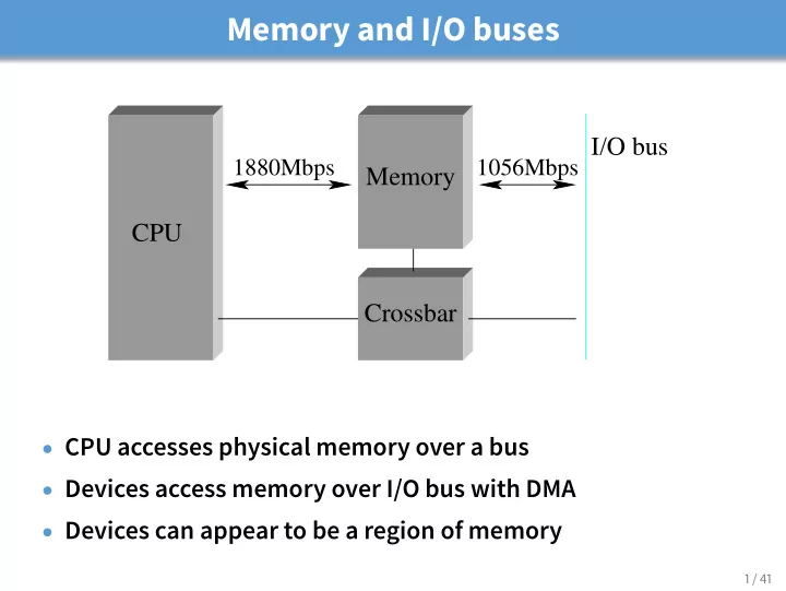
I/O bus
1880Mbps 1056Mbps
Crossbar Memory CPU
- CPU accesses physical memory over a bus
- Devices access memory over I/O bus with DMA
- Devices can appear to be a region of memory
1 / 41