
SLIDE 1
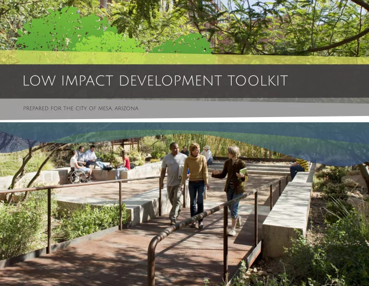
LOW IMPACT DEVELOPMENT TOOLKIT
prepared for the city of mesa, arizona
LOW IMPACT DEVELOPMENT TOOLKIT prepared for the city of mesa, - - PowerPoint PPT Presentation
LOW IMPACT DEVELOPMENT TOOLKIT prepared for the city of mesa, arizona Development Impacts and Challenges FLOODING HEAT-ISLAND EFFECT INCREASE POLLUTANT AND SEDIMENT LOADS INCREASED COSTS OF STORM WATER INFRASTRUCTURE INCREASED PRESSURE ON
prepared for the city of mesa, arizona
FLOODING HEAT-ISLAND EFFECT INCREASE POLLUTANT AND SEDIMENT LOADS INCREASED COSTS OF STORM WATER INFRASTRUCTURE INCREASED PRESSURE ON EXISTING STORM WATER INFRASTRUCTURE
REDUCES FLOODING MITIGATES HEAT-ISLAND EFFECT REDUCES SEDIMENT AND POLLUTANT LOADS REDUCES COSTS OF STORM WATER INFRASTRUCTURE IMPROVES LIVABILITY AND ADDS VALUE TO THE COMMUNITY
VISIBLE and USEFUL IMPACTS DEVELOPABLE AREA ON-SITE ECONOMIC VALUE and SAVINGS
LID toolkit diagram
method of managing stormwater runoff means to accomplish actions
S O U R C E A C T I O N T O O L S T E C H N I C A L V A R I A T I O N S
ALTERNATIVE SOURCES HARDSCAPE AREAS STRUCTURE RUNOFF LANDSCAPE AREAS PARKING & STREETS REUSE INFILTRATE FILTER EVAPO- TRANSPORATE CONVEY STORE
Cisterns Above Ground Cisterns Below Ground Tree Preservation Soil Amendment Impervious Surface Reduction Plant Selection Standard Curb Cut Curb Cut with Sidewing Concrete Flush Curb Grated Curb Cut Curb Cut with Sediment Capture Wheelstop Curb Vegetated Retention Basin Bioretention Cell Planter Constructed Wetlands Meandering
Linear Restored Wash Stabilized Aggregate Porous Asphalt Porous Concrete Structural Grids Permeable Pavers Rooftop Garden Downspout Disconnection Infiltration & Underdrains
* Not in tookit because it is applicable to all other tools *
6 low impact development toolkit
Description
impervious surface, such as roads, parking lots, or hardscape areas, to flow into a lower landscaped storage and infjltration area (LID facility).
green infrastructure practices without major reconstruction.
the street, they will usually collect only a portion of the water flowing along the gutter. If attenuating stormwater flows along the street is the goal, place multiple curb cuts at intervals along the street.
Installation
preferred for ease of maintenance.
stormwater velocity and volume, and the capacity of the area behind curb for detention, infjltration and access to overflow systems.
is to create a smooth transition from the paved surface to full curb height.
Maintenance
free flow of stormwater into LID facility (1-2 times per year and after storm events).
reinforce as necessary (annually and after storm events).
not have steep side slopes that might erode.
landscape area.
fjnish grade of the landscape area to allow for passage of sediment.
side of the curb cut opening to reduce the potential for erosion in landscaped areas.
Footnote: #1
Green street - standard Curb Cut
Functions
Flow Control Filtration Detention Infjltration Retention Treatment
Location Benefits
Shade Habitat Recreation Aesthetics Design Innovation Education Heat-Island Relief Street Buffer Street Median Parking Island Driveway Parking Lot Pedestrian Path Residential Building Parking Shading Structure Nonresidential Building Residential Landscape Parks & Open Space Reduce Impact on Infrastructure
Curb cuts control stormwater flow from streets to LID facilities.
Nonresidential Landscape
10 low impact development toolkit
Chapter 2
Flow Control Filtration Detention Infjltration Retention Treatment Shade Habitat Recreation Aesthetics Design Innovation Education Heat-Island Relief Street Buffer Street Median Parking Island Driveway Parking Lot Pedestrian Path Residential Building Parking Shading Nonresidential Building Residential Landscape Parks & Open Space Reduce Impact on Infrastructure
Green street - WHEELSTOP CURB
Functions Location Benefits
Wheelstops allow sheet drainage to pass into landscape areas.
Description
They allow stormwater from adjacent impervious surfaces, like parking lots, to flow into adjacent planting areas.
be used to defjne openings and protect infjltration and planting areas.
Installation
conditions while allowing water to flow into vegetated areas.
applications, but they can also be applied in certain street conditions.
wheelstop curb edge and edge of asphalt paving to provide structural support for the wheel stop.
structural support of poured-in-place wheel stop curbs and visual demarcation of parking area or driveway edge.
Maintenance
as other poured concrete curbs. Unless they are fjrmly anchored they can be dislodged creating unsightly and dangerous conditions. They should be check regularly for cracking and settlement and repaired or replaced as necessary.
Nonresidential Landscape
low impact development toolkit 15 Footnote: #3
Case Study – Taxi Mixed Use Development, Denver, CO
Flow Control Filtration Detention Infjltration Retention Treatment Shade Habitat Recreation Aesthetics Design Innovation Education Heat-Island Relief Street Buffer Street Median Parking Island Driveway Parking Lot Pedestrian Path Residential Building Parking Shading Nonresidential Building Residential Landscape Parks & Open Space Reduce Impact on Infrastructure
Green street - Grated Curb Cut
Functions Location Benefits
Grates allow stormwater to pass through while proving an accrossing pedestrian route.
Nonresidential Landscape
12 low impact development toolkit
Description
stormwater from impervious surfaces to flow into a landscaped area.
pedestrian traffjc and the need for handicap accessible routes adjacent to streets and parking areas.
distance to install a scupper. Where they are used, only decorative heavy duty, accessible, precast gratings should be permitted.
Installation
minimize the potential for clogging.
(ADA) and have adequate slip resistance.
the fjnish grade of the landscaped area to allow for the passage of
where concentrated runoff from the channel is deposited into the landscaped area.
Maintenance
the free flow of stormwater (1-2 times per year and after storm events).
that may cause ponding of water or impede accessible pedestrian routes.
Footnote: #4
Chapter 4
Water features can harvest rainfall, making water visible and celebrating its importance in an arid climate. Porous pavers and permeable pavement at the pedestrian walkway allows infjltration and reduces off-site runoff. Standard curb cuts open up planting areas to receive stormwater flow. Grated curb cuts convey stormwater from pavement nto planting areas.
low impact development toolkit 49
Location
Flow Control Filtration Detention Infjltration Retention Treatment Shade Habitat Recreation Aesthetics Design Innovation Education Heat-Island Relief Street Buffer Street Median Parking Island Driveway Parking Lot Pedestrian Path Residential Building Parking Shading Structure Nonresidential Building Residential Landscape Parks & Open Space Reduce Impact on Infrastructure
Green street - Concrete Flush Curb
Functions Benefits
Flush curbs allow stormwater to sheet drain to landscape areas.
Description
directly into landscaped areas and stormwater facilities. Stormwater flow is distributed more evenly which reduces the potential for erosion and clogging along a pavement edge.
Installation
surface, with allowances for subgrade compaction and future settlement.
fjnished grade of the landscaped area to allow for passage of sediment and debris to drop out.
adjacent areas to reduce the portential for erosion.
important visual cue when used on roads, driveways and bicycle paths.
way, per Mesa’s Suburban Ranch Street Detail.
Maintenance
that may cause water to pond or backup.
Nonresidential Landscape
14 low impact development toolkit Footnote: #6
Flow Control Filtration Detention Infjltration Retention Treatment Shade Habitat Recreation Aesthetics Design Innovation Education Heat-Island Relief Street Buffer Street Median Parking Island Driveway Parking Lot Pedestrian Path Residential Building Parking Shading Structure Nonresidential Building Residential Landscape Parks & Open Space Reduce Impact on Infrastructure
Vegetated Swale - Meandering or Linear
Functions Location Benefits
Vegetated swales accept stormwater for conveyance, storage and infjltration.
Nonresidential Landscape
16 low impact development toolkit
Description
provide an alternative to piped storm sewers.
sewer inlets or directly to surface waters.
fjrst flush of stormwater runoff and promoting infjltration of storm flows they convey.
used in place of underground piping.
Installation
reduce erosion and maintenance requirements.
greater than one-half inch per hour. Soil Amendments may be needed to achieve ideal infjltration rates.
not exceed 4:1. Slopes adjacent to walkways or accessible hardscape areas should not exceed 6:1. In suburban contexts, a meandering
Maintenance
plants.
swale shape and volume over time. As with plant waste, sediment should be removed and disposed of properly. installation should be used. Linear installations are appropriate in urban contexts.
rail requirement. In any case, a vertical drop of more than 30 inches will require a guard rail installation.
Footnote: #7
Chapter 2
Flow Control Filtration Detention Infjltration Retention Treatment Shade Habitat Recreation Aesthetics Design Innovation Education Heat-Island Relief Street Buffer Street Median Parking Island Driveway Parking Lot Pedestrian Path Residential Building Parking Shading Nonresidential Building Residential Landscape Parks & Open Space Reduce Impact on Infrastructure
Bioretention - Bioretention Cell
Functions Location Benefits
Bioretention cells fjt into constrained urban site.
Nonresidential Landscape
low impact development toolkit 19
Description
plants adapted to the local climate and soil conditions. These are used in more urban conditions and where subsoils are porous and allow infjltration into the subgrade.
below the cell and have an overflow that carries excess stormwater to a discharge point.
include an underdrain, are called bioretention planters.
Installation
bottom surface should be loosened several inches deep prior to placing the bioretention soil mix. The cell bottom area should be designed based
A pre-settling area can be a rock or vegetated sediment capture area designed to protect the bioretention cell by slowing incoming flows at the point of entry.
function of a bioretention cell.
establishment, regulate soil moisture and temperature, and add organic matter to the soil.
Maintenance
vegetation and removing weeds regularly. Do not use herbicides in stormwater facilities.
below the design flow capacity, Check percolation rates if bioretention cells are not draining within 36 hours, or have been contaminated by sediment inflows. Footnote: #10
settles out particulates such as sediment, and provides for uptake and fjltering of pollutants within the cell.
saturation.
an approved discharge point.
Case Study – Lincoln Ave. Redevelopment – Denver, CO
Conventional Stormwater Pipe System Reduced Stormwater Pipe System
Bioretention - Planters
Functions Location Benefits
Flow Control Filtration Detention Infjltration Retention Treatment Shade Habitat Recreation Aesthetics Design Innovation Education Heat-Island Relief Street Buffer Street Median Parking Island Driveway Parking Lot Pedestrian Path Residential Building Parking Shading Structure Nonresidential Building Residential Landscape Parks & Open Space Reduce Impact on Infrastructure
Bioretention planters provide stormwater storage and promote healthy growth of trees and plants.
Nonresidential Landscape
20 low impact development toolkit
Description
in porous planting soils and above the soil surface. Planters may be raised above ground or can be set flush with or even below the ground
barrels.
plants with a minimum of supplemental irrigation, while improving the quality of stormwater runoff and reducing runoff volume.
Installation
space in each planter.
maximize storage.
proper physical composition, adequate drainage and organic matter to support designated plantings. Planting soil should be at least 18” deep; contain no more than 20% compost, and be a desert-appropriate mix.
Maintenance
storage, and drainage functions.
standing water is not present in the planter for more than 36 hours.
maintenance practices. Prune and replace plants as necessary.
planters that have structured soils or Silva Cells.
size of specifjed plantings. A subgrade gravel layer can be used to add storage capacity. Footnote: #11
Chapter 2
Permeable Paving - Porous Concrete
Functions Location Benefits
Flow Control Filtration Detention Infjltration Retention Treatment Shade Habitat Recreation Aesthetics Design Innovation Education Heat-Island Relief Street Buffer Street Median Parking Island Driveway Parking Lot Pedestrian Path Residential Building Parking Shading Nonresidential Building Residential Landscape Parks & Open Space Reduce Impact on Infrastructure
Porous concrete can reduce runoff sustaining in sidewalks and plaza areas.
Nonresidential Landscape
low impact development toolkit 23
Description
special mix design with void spaces that make it highly permeable.
narrow limits to ensure porosity,.
delivered into storm sewer system and can reduce contaminants in runoff prior to its discharge to the storm sewer system
Installation
experienced contractor. Poor materials and/or installation can result in a higher risk of failure.
compacted sub-base, geotextile, a reservoir stone aggregate, and poured surfacing layer, formed with a screed fjnish.
grades.
system through underdrain tile or piping, especially if the subgrade does
Maintenance
sediment and minimize clogging. With regular maintenance, porous concrete can have a service life of at least 20 years.
cracking, and damaged areas repaired to match the original pavement design. Footnote: #14 not allow adequate infjltration. Underdrain tile or piping is sometimes necessary to achieve proper drainage.
LID ‐ The New Normal in Site Design – August 15th, 2014
LID ‐ The New Normal in Site Design – August 15th, 2014
th
LID ‐ The New Normal in Site Design – August 15th, 2014
LID ‐ The New Normal in Site Design – August 15th, 2014
Chapter 2
Permeable Paving - Permeable Pavers
Functions Location Benefits
Flow Control Filtration Detention Infjltration Retention Treatment Shade Habitat Recreation Aesthetics Design Innovation Education Heat-Island Relief Street Buffer Street Median Parking Island Driveway Parking Lot Pedestrian Path Residential Building Parking Shading Nonresidential Building Residential Landscape Parks & Open Space Reduce Impact on Infrastructure
Permeable paving is an attractive way to provide runoff reduction in paving and pedestrian areas.
Nonresidential Landscape
low impact development toolkit 25
Description
designed to be set on a compacted base and highly permeable setting bed with joints fjlled with sand or fjne gravel.
storm system via underdrain piping.
subgrade, or allow it to evaporate providing local air cooling.
sediments and pollutants.
Installation
as porous pavers. The depth of rock and gravel must be capable of holding rainwater long enough for the soil underneath to absorb it.
vibratory compactor, and install geotextile fabric.
the crushed rock in separate layers and recompact. Install bedding layer and then paving stones with edge restraints.
Maintenance
broken pavers immediately to prevent structural instability. Pavers can be removed individually and replaced during utility work.
should be performed when paver areas are dry.
unit pavers are the most effective at reducing runoff and are often the most aesthetically pleasing option. Footnote: #16
Green Roofs - Rooftop Garden
Functions Location Benefits
Flow Control Filtration Detention Infjltration Retention Treatment Shade Habitat Recreation Aesthetics Design Innovation Education Heat-Island Relief Street Buffer Street Median Parking Island Driveway Parking Lot Pedestrian Path Residential Building Parking Shading Structure Nonresidential Building Residential Landscape Parks & Open Space Reduce Impact on Infrastructure
Green roofs store and utilize stormwater to reduce runoff from building sites.
Nonresidential Landscape
28 low impact development toolkit
Description
vegetation planted over a waterproofjng membrane. It may also include a root barrier, drainage mat and irrigation system.
difference is in the depth of soil and the ability to support simple groundcover planting (intensive) versus larger materials such as trees and shrubs (extensive).
from buildings, and insulate buildings from solar gain and heat loss.
Installation
design.
the sun and shading by surrounding buildings will all impact types of materials used and maintenance requirements. Views to and from the roof will also determine where elements are located for maximum effect.
green roof. A qualifjed architect, structural engineer, landscape architect and facility maintenance personnel are critical to the success of a green roof project.
Maintenance
plants should be used in our desert environment. Depending on whether the green roof is extensive or intensive, required plant maintenance will range from two to three yearly inspections to check for weeds or damage, to weekly visits for irrigation, pruning, and replanting.
membrane are required.
the building architect, structural engineer and/or owner should specify and maintain everything up to and including the waterproof membrane. The greenroof designer and installer is only responsible for those items above the waterproof membrane, including soils, drainage and plantings. Footnote: #19
maintenance, but also for delivery of materials, soil and plants.
Chapter 4
Green roof absorbs rainwater, provides insulation and creates a habitat for birds. It also helps to lower adjacent air temperature mitigating the heat island effect. Native materials, used in urban forms, help create a gathering area for people using the Tempe Transit Center. Native tree canopies provide colling in the plaza area. Shade structures at transit stations can harvest rainwater and use it to nourish a green wall.
low impact development toolkit 53
Chapter 2
Green Roofs - Downspout Disconnection
Functions Location Benefits
Flow Control Filtration Detention Infjltration Retention Treatment Shade Habitat Recreation Aesthetics Design Innovation Education Heat-Island Relief Street Buffer Street Median Parking Island Driveway Parking Lot Pedestrian Path Residential Building Parking Shading Nonresidential Building Residential Landscape Parks & Open Space Reduce Impact on Infrastructure
Disconnecting a downspout allows rainwater to supplement irrigation in the landscapes.
Nonresidential Landscape
low impact development toolkit 29
Description
rooftop into a landscaped yard instead of into a piped system or into the street.
and used to irrigate landscape plants or infjltrate into the ground.
Installation
adjacent properties to avoid structural damage or nuisance flooding.
direct downspout drainage to landscaped areas.
floor elevation to reduce the potential for building flooding.
Maintenance
repair with spikes or place new hangers as needed.
Each elbow or section of the downspout should funnel into the one below it. All parts should be securely fastened together.
materials near the building that might inhibit positive drainage. Footnote: #20
Chapter 4
A new entry and garden/outdoor classroom provide cleansing garden for adjacent building and pavemnt runoff. Stormwater runoff is reduced signifjcantly in the landscape and fully integrated with building mechanical systems. Pedestrian walkways provide shady comfort.
low impact development toolkit 55
Rainwater Harvesting - Cisterns above Ground
Functions Location Benefits
Flow Control Filtration Detention Infjltration Retention Treatment Shade Habitat Recreation Aesthetics Design Innovation Education Heat-Island Relief Street Buffer Street Median Parking Island Driveway Parking Lot Pedestrian Path Residential Building Parking Shading Structure Nonresidential Building Residential Landscape Parks & Open Space Reduce Impact on Infrastructure
Cisterns can store rainwater to be re-used for future landscape irrigation.
Nonresidential Landscape
30 low impact development toolkit
Description
runoff, often from a rooftop, and stores the water for later use.
including a gutter system that collects runoff from the rooftop and directs it into the cistern, a cistern that stores runoff for later use, an overflow pipe that allows excess runoff to leave the cistern in a controlled manner, and an outlet pipe, sometimes connected to a pump, that draws water from the bottom of the cistern for irrigation use.
Installation
greatest impact on system cost and performance. Several factors must be considered, including contributing rooftop area, rainfall patterns and anticipated usage.
the gutter downspouts. It is generally easiest and most cost effective to place the cistern near an existing downspout. When possible, locate the cistern near the site where water will be used.
required to provide structural support to an aboveground cistern.
Maintenance
rainwater harvesting system.
the surface and that there are not holes allowing mosquitoes or other insects to enter the cistern.
Clean out debris twice a year, preferably prior to the beginning of each rainy season.
breeding.
cistern has reached its capacity.
be installed.
a cistern. Footnote: #21
low impact development toolkit 33
Chapter 3
Current Practice Recommended LID Option
Best Practice
low impact development toolkit 35
Chapter 3
Sloped Grated Stormwater Sediment Capture and Bioretention Existing Stormwater Catchment Sloped Grated Stormwater Sediment Capture and Bioretention Section Details
Best Practice
Current Practice Recommended LID Option
low impact development toolkit 37
Chapter 3
Permeable Pavement Existing Concrete Paving Permeable Pavement Section Details
Best Practice
Current Practice Recommended LID Option
low impact development toolkit 39
Chapter 3
Standard Curb Cut Existing Standard Curb Standard Curb Cut Plan Details Standard Curb Cut Section Details
prepared for the cities of mesa and Glendale By the Team of: With Funding From:
Water Infrastructure fjnance authority
FEBRUARY 2015
90 low impact development toolkit