SLIDE 1 Light Emitting Diodes (LEDs)
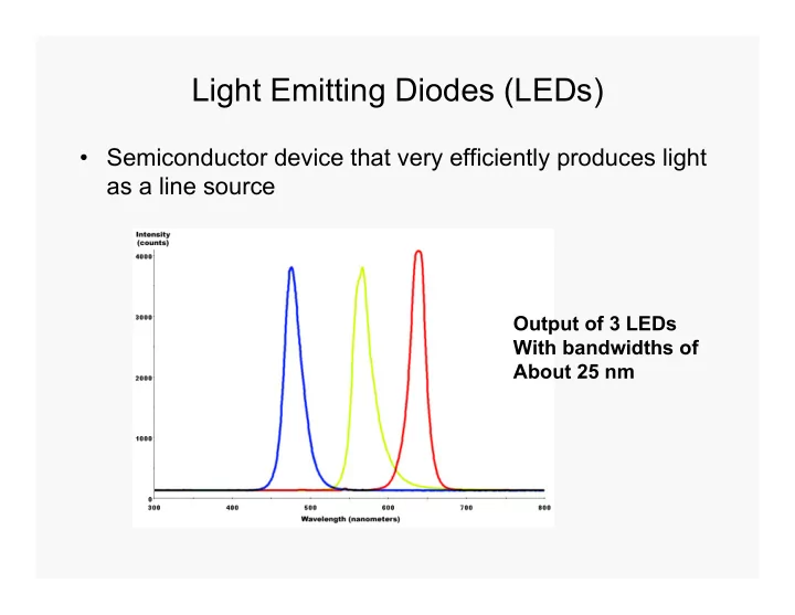
- Semiconductor device that very efficiently produces light
as a line source
Output of 3 LEDs With bandwidths of About 25 nm
SLIDE 2
LED Packages
SLIDE 3 Older Communications LED
Fiber optic pig tail
SLIDE 4 LED Radiation Patterns
An LED is a directional light source, with the maximum emitted power in the direction perpendicular to the emitting surface. The typical radiation pattern shows that most of the energy is emitted within 20°
maximum light. Some packages for LEDs include plastic lenses to spread the light for a greater angle of visibility.
SLIDE 5 LED Device Structure
(Edge Emitting LED) One type of LED construction is to deposit three semiconductor layers on a substrate. Between p-type and n-type semiconductor layers, an active region emits light when an electron and hole recombine. The light is produced by a solid state process called
- electroluminescence. In this particular design,
the layers of the LED emit light all the way around the layered structure, and the LED structure is placed in a tiny reflective cup so that the light from the active layer will be reflected toward the desired exit direction.
SLIDE 6
Two Basic Device Designs
SLIDE 7 Wavelength Selection
Three main approaches: 1) Block off unwanted radiation –
2) Disperse radiation & select desired band – monochromator 3) Modulate wavelengths at different frequencies - interferometer FILTERS
1) Absorption – colored glass, colored film, colored solutions – cheapest way
SLIDE 8
Assortment of Glass & Quartz Optical Filters
SLIDE 9
Combining two appropriate cut-off filters produces a bandpass filter. The example shown here comes from 3 filters producing bands at 500 & 600 nm.
SLIDE 10
Two terms associated with optical filters are: 1) Effective bandwidth measured at ½ peak height 2) Nominal wavelength These filters have nominal wavelengths of 450 & 500 nm
SLIDE 11 2) Interference filters – usually Fabrey-Perot type
Incident light beam Transmitted radiation Glass layers Dielectric material (CaF or MgF) Semi-reflective metal layers
Light bounces back & forth & gets out of phase with itself unless it meets conditions for constructive interference
SLIDE 12 Condition for constructive interference mλ 2d = ------ η If distance (d) is multiple (m) of wavelength (λ) then it won’t be interfered with Concept of Order – constructive & destructive interference causes waves with different phase angles to be eliminated except if they are multiples of each other
distance between semi-reflective layers
refractive index
SLIDE 13 2) Interference filters – usually Fabrey-Perot type
Incident light beam Transmitted radiation Glass layers Dielectric material (CaF or MgF) Semi-reflective metal layers
Light bounces back & forth & gets out of phase with itself unless it meets conditions for constructive interference
“d” spacing
d
SLIDE 14 Condition for constructive interference mλ 2d = ------ η If distance (d) is multiple (m) of wavelength (λ) then it won’t be interfered with Concept of Order – constructive & destructive interference causes waves with different phase angles to be eliminated except if they are multiples of each other
distance between semi-reflective layers
refractive index
SLIDE 15
FWHM – full width at half maximum
SLIDE 16
Transmittance vs. wavelength for typical Fabrey-Perot Interference filter showing first and second order λ’s (m = 1 & m = 2)
SLIDE 17
3) Neutral density filters – reduces intensity without any λ discrimination
SLIDE 18 II) MONOCHROMATORS
source detector location Simple Prism Monochromator Entrance slit allows source radiation to illuminate the first lens which collimates the light spreading it across the face of the
- prism. Prism disperses radiation into component wavelengths
and the second lens focuses the spectrum at the focal plane. An exit slit selects the band of radiation to reach the detector. Dispersing element can be a prism or a diffraction grating. Focusing elements can be lenses or mirrors.
Focal plane
SLIDE 19
- Optical Materials – need optically
transparent materials for lenses, prisms & sample cells
- In visible region – can use glass down to
350 nm
- In the UV region – quartz is material of
choice
- In the IR region – NaCl, KBr, etc. The
heavier the atoms of the salt, the farther into the IR region (i.e., longer λ) before significant absorption occurs Problem – sensitivity to moisture
SLIDE 20 Resolution – ability to distinguish as separate, nearly identical frequencies; measured in terms of closest frequencies Δν in a spectrum that are distinguishable ν λ R = -----
(both dimensionless) Δν Δ λ Dispersion – spread of wavelengths in space Angular Dispersion – angular range dθ over which waveband dλ is spread dθ rad
dλ nm
SLIDE 21 Linear Dispersion – distance dx over which a waveband dλ is spread in the focal plane of a monochromator dx mm
dλ nm Linear Reciprocal Dispersion – range of λ’s spread over a unit distance in the plane of a monochromator dλ nm
dx mm Related terms spectral slit width or bandwidth or bandpass = range of λ’s included in a beam of radiation measured at half max intensity
SLIDE 22 Lenses – lens equation (for a thin lens) 1 1 1
r2
Where f = focal length η = refractive index of lens material η’ = refractive index of adjacent material r1 = radius of curvature of first surface r2 = radius of curvature of second surface 1 1 1
i o
image
i
distance to image distance to object
SLIDE 23 Focal length is important specification of a monochromator focal length (f) f/ (f number) = ------------------------------ lens clear aperature
- f/ is measure of light gathering power
- Larger f/ means getting less light
- Light gathering power ~ 1/(f/)2
Point source at f (focal point
Parallel beams
SLIDE 24 Mirrors – high quality instruments use front- surfaced mirrors for focusing which avoids chromatic aberrations
1 1 1
+ ----- f i o
Problem spherical aberrations
image
i
Spherical Mirror
SLIDE 25 Mirror problem spherical aberrations – f gets shorter as rays go off axis (this can actually be a problem for lenses also) Several solutions: 1) Just use center of mirror (or lens) – but this reduces the light-gathering power (f/ increases) 2) Use parabolic mirror (harder to make $$) 3) Use Schmidt Corrector
so they come to a good focus
Spherical Mirror
SLIDE 26
Astigmatism – for an object off axis, the horizontal and vertical focuses differ – get two images displaced from each other Numerical Aperture (NA) = sin θ angle over which a device accepts light Slits – entrance and exit slits Slits affect energy throughput & resolution Decrease slit width gain resolution & lose energy throughput Open slits wider increase signal (throughput) but lose resolution θ
SLIDE 27
Energy throughput must be sufficient for detector to measure signal with adequate precision. In practice the image of the entrance slit in a monochromator should just fill the exit slit for optimum conditions. Otherwise the larger slit establishes (i.e, limits) the resolution and the smaller slit establishes (or limits) the energy throughput. There is a theoretical minimum for slit widths imposed by diffraction.
SLIDE 28 Light exiting a monochromator exit slit has a triangular distribution Optical Efficiency = throughput x resolution Good criterion for comparing optical systems Prism < Grating < Interferometer Monochromator Monochromator
Relative power
Range of λ’s passing when set at λo bandpass or bandwidth
SLIDE 29 Dispersion Devices 1) Prisms Light bends due to η η = f f (λ) dθ dθ dη Angular Dispersion = ----- = ------ x ------ dλ dη dλ Angle changes with λ the larger the better
b A
θ
A = apical angle b = base length function of prism design (i.e. angle A) function
material
SLIDE 30
Dispersion Devices 1) Prisms dθ Increasing A ----- increases but internal dη reflection is also greater (typical A value is 60o)
b A
θ
A = apical angle b = base length
SLIDE 31 Dispersion Devices 1) Prisms
dη dη
- ---- depends on material, ----- greatest at shorter λ
dλ dλ
b A
θ
A = apical angle b = base length
η λ
SLIDE 32 mm dθ Linear Dispersion
nm dλ Depends on angular dispersion and focal length For constant bandwidth, slit widths must be varied with λ to compensate for variations in dη/ dλ Stated another way, linear dispersion changes in different regions of the spectrum
SLIDE 33
Kinds of Prisms Littrow Prism & Mounting – compact design
Focal Plane Reflecting Prism
SLIDE 34 Problem with quartz prisms is that quartz is
- ptically active (optically anisotropic). With
the Littrow prism or any reflecting prism, the light travels essentially the same path in both directions and this effect is eliminated. Cornu Prism
Right handed quartz Left handed quartz 60o 30o (-) (+)
SLIDE 35
f/ of a monochromator is important if have a weak source. For lenses in series, the smallest f/ sets the overall f/ for the system. Lens Summary: 1) rugged, easy to use, inexpensive 2) can have chromatic aberrations = focal length depends on η which varies with λ – solution is to fabricate lenses out of a composite glasses so η is constant with λ. This increases cost 3) Each lens results in some light loss due to reflection
SLIDE 36
Another view of a Cornu prism
SLIDE 37 Gratings – based on diffraction & interference Transmission Gratings & Reflection Gratings consist of a series of grooves in glass or quartz
Monochromatic Radiation Grating
d
SLIDE 38
Gratings work on the principles of diffraction & interference
SLIDE 39
Grating Equation m λ = d sin β Condition for constructive interference AC = extra distance light travels for first order = d sin β For higher orders the distance gets longer
d
SLIDE 40
Reflection grating with non-normal incidence