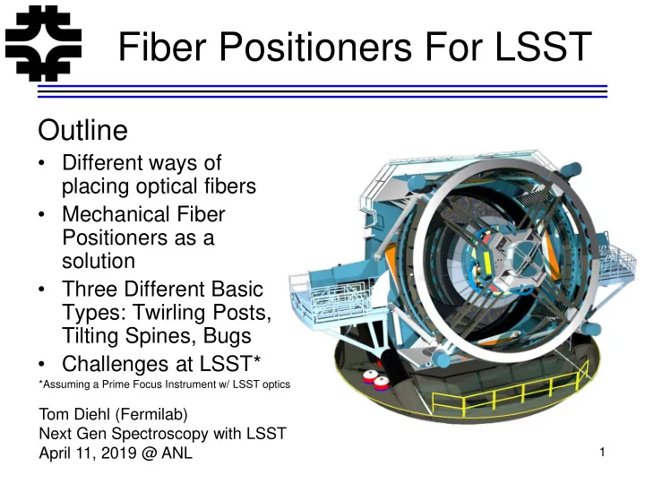
Fiber Positioners For LSST Outline Different ways of placing - - PowerPoint PPT Presentation

fiber positioners for lsst
SMART_READER_LITE
LIVE PREVIEW

Fiber Positioners For LSST Outline Different ways of placing - - PowerPoint PPT Presentation

Fiber Positioners For LSST Outline Different ways of placing optical fibers Mechanical Fiber Positioners as a solution Three Different Basic Types: Twirling Posts, Tilting Spines, Bugs Challenges at LSST* *Assuming a Prime


slide-1
SLIDE 1

1

Fiber Positioners For LSST

Outline

  • Different ways of

placing optical fibers

  • Mechanical Fiber

Positioners as a solution

  • Three Different Basic

Types: Twirling Posts, Tilting Spines, Bugs

  • Challenges at LSST*

Tom Diehl (Fermilab) Next Gen Spectroscopy with LSST April 11, 2019 @ ANL

*Assuming a Prime Focus Instrument w/ LSST optics

slide-2
SLIDE 2

Acknowledgements

  • Steve Kent, Kyler Kuehn, Joe Silber, Will Saunders,

Michael Schubnell, Greg Tarle, Matthew Colless, Daren DePoy, Jennifer Marshall, Ting Li, Klaus Honscheid

2

  • Jan. 2019
slide-3
SLIDE 3

How many spectra?

3

eather Exp/Night Nights Fibers Objects

W N N N N =

  • Some LSST Survey Characteristics
  • 18,000 square degrees
  • Mag limits

– r<24.5 single epoch exp. – r<27.8 for 825 exp. Stacked => 20 Billion galaxies

  • Acquiring 500M spectra demands high multiplexing. 20,000 is a

reasonable number to start with.

  • A Tough Problem:

– DECAM Plate Scale (0.26 arcsec/15 microns): 0.1” position accuracy corresponds to 6um. 1’ target separation is 3.6 mm spacing – Fast reconfiguration, maximum throughput, highly reliable, cheap, easy to manufacture …

slide-4
SLIDE 4

Plug Plates

  • Plates are prepared in advance by drilling

holes in the imaged locations of targets

  • A person plugs fibers from a harness into

the plate and an illumination trick is used to determine which fiber is in which hole

  • A plate is useful only for one configuration

and for a limited time at night

  • If it costs ~$0.12 per plug to cast a plate

($50 for a plate of 5000 plugs), drill holes ($0.05 each), and have a person plug in fibers (one plate per 8hrs), then ½ billion

  • bject-visits costs ~$60M.
  • A robot might make this reasonably

economical but how do we stack and change plates? I didn’t try to solve that.

4

Rich Kron? SDSS

slide-5
SLIDE 5

Pick & Place Robot

  • AAΩ is a 492-fiber

spectograph at Prime Focus

  • f AAT
  • Commissioned in 2006
  • A robot picks up each fiber

and places on the FP.

  • Looks like there is a 45 deg

mirror on the end of each fiber.

  • They use two plates, observe
  • n one, configure the next
  • Limitation in #’s is due to

space and complexity

5

slide-6
SLIDE 6

Integral Field Units A bundle of optical fibers in a 2D array

  • 31M fibers arranged in a

hex close-packed array would fully populate a 64 cm diameter focal plane.

  • But then there’s a sorting

problem on the other end.

  • The issues might include

the length of fibers and the robustness of connectors.

  • I didn’t try to solve that.

6

https://www.sdss.org/instruments/manga-instrument/

slide-7
SLIDE 7

Mechanical Fiber Positioners Move the Optical Fiber to the Object

  • Twirling Posts
  • Tilting Spines
  • Bugs

7

slide-8
SLIDE 8

Cobra “Twirling Post”

  • One Fiber Tip is held on an rotating

arm at the top of a rotating post.

  • Piezoelectric driven “wobbly motors”
  • PSF Cobras ~ 7.7 mm diameter
  • PSF will have 2400 F.P.s with 8mm

hex close-pack spacing

8

“Patrol Radius” 9.5 mm (I suspect that’s really the diameter)

https://pfs.ipmu.jp/instrumentation.html https://www.newscaletech.com/app-note-cobra-two-dof-fiber-optic-positioning-robot/

Subaru Prime Focus Spectrograph

slide-9
SLIDE 9

DESI “Twirling Post”

9

DESI Petal (one of 10) 5000 F.P. 1 cm pitch

  • Fiber is held on an rotating arm at the top
  • f a rotating post.
  • DESI F.P. ~ 8 mm diameter, 10.4 mm

pitch, PR = 6 mm, 812 mm diameter focal plane.

  • Big Focal Plane will have 5000 F.P.s
  • Lots of wee moving parts including two

DC Brushless Gear Motors

slide-10
SLIDE 10

“Tilting Spines”

10 400 fiber FMOS Echidna is still on the Subaru

  • FMOS (400), 4MOST (2436), DESpec (4000),

MSE (4332)

  • Piezo tube and magnetic cup fits over the ball on

the spine. One moving part.

  • 4MOST soon to go online?

– 2 minute configuration time – 9.5 mm pitch, 11.8 mm patrol radius

  • DESpec/MSE even smaller pitch: 6.7/7.6 mm
  • Could put more than one fiber in a spine
slide-11
SLIDE 11

Tilting Spine Movement

  • Uses ~100V sawtooth wave on piezos to bend

and unsnap the base. The ball slips in the cup and sticks, thus nudging the tip a little. Apply the pulse a bunch of times to get the desired position.

  • Spine Tips can be located to 0.7 mm from each
  • ther

Will Saunders et al., “MOHAWK …” Proc. SPIE 8446, 84464W (2012).

  • A. Sheinis et al., Proc. SPIE 9151, 91511X (2014).

DESPec “Mohawk” 4000 spines

slide-12
SLIDE 12

Tilting Spines New Piezo Design (2016)

  • Same spine. New piezo geometry. Still “slip-stick” movement
  • Now low voltage and more precision.
  • June & July 2018 discussions with Will Saunders (AAO) & Kyler Kuehn

(AAO) suggest that 5 to 6mm pitch is possible. R&D needed here.

Jaime Gilbert & Gavin Dalton, “Echidna Mark II: one giant leap for 'tilting spine' fibre positioning technology”, Proc. SPIE 9912, 992012 (2016).

slide-13
SLIDE 13

StarBugs

  • A positioner that carries a fiber close to

a glass focal surface. Held to the glass by a slight vacuum.

  • Uses concentric piezos to perform a lift

& step motion so that the bug can “walk”.

  • Bug Footprint ~ 10 mm
  • Can have different size bugs, multiple

fibers, mini-IFUs …

  • Difficult to make them much smaller?

13

TAIPAN instrument soon to have 150-300 fibers

slide-14
SLIDE 14

LSST Imaging Camera Optics (Wikipedia)

  • LSST

– 8.4m (6.7m) mirror w/ a hole in the center – 9.6 square-degree FoV – Focal plane is flat & 64 cm diameter – ~6 deg edge non-telecentricity – Plate scale is 50.9 microns per arcsec

14

slide-15
SLIDE 15

Application to LSST Problem: f/1.2 beam

  • Fibers transmit light

through total internal reflection.

  • For f/1.2, θ= 24.6 deg
  • For f/2.3, θ= 12.5 deg
  • For LSST we’ll need to

put a lens on each fiber tip (See Chris S., probably).

  • Better throughput with

beams with f #’s of ~3+ (next slide)

15 https://www.photonics.com/Articles/Fiber_Optics_Understanding_the_Basics/a25151

η Core = 1.5 η Cladding = 1.485 θ=12.2 deg

slide-16
SLIDE 16

Throughput & FRD vs. F Ratio

  • F. Ramsey Tested

Focal Ratio Degradation and throughput vs input focal ratio and output focal ratio for various diameter fibers.

  • Bigger fibers => more

throughput.

  • Concludes f/3 to f/4 is

ideal.

16

  • F. Ramsey, “Focal ratio degradation in optical fibers of astronomical interest” ,

Proceedings of the Conference Fiber Optics in Astronomy, 1988. Also see Will Saunders SPIE paper on DESpec Mohawk

F/3

slide-17
SLIDE 17

Tilting Spines Defocus w/ Tilt How bad is f/1.2?

  • A. The fiber tip moves in an arc. If the spine

is tilted, the fiber tip is not in the focal plane.

– For L=250 mm spine with Patrol Radius 8 mm (6.7mm pitch), ∆H = 128 µm. – So we put a focal plane ∆H/2 = 64 µm below the top of the non-tilted fibers.

  • B. LSST has f/1.2 incoming beam (skip the

lenslet for this estimate)

– For ∆H/2 = 64 µm and Θin = 25°, the radius of the

  • ut of focus spot is 29 µm.

– That’s smaller than the fiber radius. This is OK. – Implication for the minimum diameter of the

  • fibers. And the mechanical assembly tolerances.

17

A. B.

slide-18
SLIDE 18

Application to LSST Problem: not telecentric (Steve Kent)

18

  • The incoming beam has a 6 (8?) deg tilt at the edge
  • But the focus is planar
  • The fiber positioner support plate might array the positioners at

different angles, but maintaining the plane of tips of the fibers.

  • Fancy machining for the “Focal Plane Support Plate” could do that.
  • You might think you would want to, except …

Small deviation from normal incidence at outer radius R=0 (field center) R=32 cm (field edge) 25° 19° 31° 25°

slide-19
SLIDE 19

Effect of Non-Telecentricity for on Focus for Both Twirling Posts & Tilting Spines, if set to accommodate the non-telecentricity

  • At R=0 this isn’t a problem.
  • At the edge of the FP, with 6
  • deg. non-telecentricity, and a

patrol radius R of ½ cm, then ∆H/2 = Rsin(Θ) = 522 µm.

  • Spot size when we are that far
  • ut of focus has radius > 240

µm. We lose ~3/4 of the light unless the fibers are that big.

  • Similar for spines.
  • Maybe better to stay normal to

the focal plane and take the non-telecentricity loss. See

  • lenslets. Maybe they help.

19

slide-20
SLIDE 20

More Fiber Positioner Components & Technical Design Considerations

  • Fiber Positioner Support Plate
  • Positioner Control Electronics

– Power requirements

– Thermal control

  • Guide and Focus CCDs
  • Fiber View Camera to measure the current

fiber position during configuration (backlight the fibers)

– Metrology Fibers on the support plate – Fiber View Camera might be located in the central hole

  • f the primary?

– Complicated because the LSST optics has a secondary and a tertiary mirror !!! – More complicated with a lenslet on it?

20

DESI FVC

slide-21
SLIDE 21

Summary

  • I described three main types of fiber positioners: Tilting

Spines, Twirling Posts, and Bugs.

– All 3 types have been or about to be used on real instruments. – To fit 20,000 of them on a 64 cm diameter focal plane, we’ll do R&D that scales down the radial space that each positioner takes up. – Tilting spines advantages: smaller, easier to make, allows denser targets, could put a few fibers in spine if desired. – Twirling Post advantages: no tilting out of plane, so a little more throughput (small effect) than spines – Bugs Advantage: easy to see how to make mini-IFUs

  • The LSST optics and corrector provide complications

– f/1.2 beam requires fibers have lenslets on them – Non-telecentricity at focal plane coupled with flat focus surface will cause light losses at larger radii. Maybe a no go to align the positioners to the incoming beam. – How do (can) we make a fiber view camera work?

  • Perhaps we should break the assumption that we have

same corrector optics.

slide-22
SLIDE 22

Extra Slides

22

slide-23
SLIDE 23

Implementation Details

23

slide-24
SLIDE 24

LSST Optics

Filters go in between L2 and L3. It looks like there is ~a 15 inch gap between L2 and L3.

24

slide-25
SLIDE 25

Space After L2

  • Is about ½ meter before the current focal plane.
  • There is room for an ADC in there.

25

slide-26
SLIDE 26

Lenses After L2

  • The Lens L3 is also the Dewar window. We get to

replace L3 with a different L3.

  • I note the DEWAR window is pretty thick. That’s

because it has to not break under 14 psi. We don’t need for it to be so thick.

  • There is also about 1” of space behind L3 in front of

the focal plane.

  • We get to put 2 lenses in that space, if that would

help.

26