
SLIDE 1 – 9 – 2018-06-04 – main –
Softwaretechnik / Software-Engineering
Lecture 9: Scenarios & Use Cases
2018-06-04
- Prof. Dr. Andreas Podelski, Dr. Bernd Westphal
Albert-Ludwigs-Universität Freiburg, Germany
– 9 – 2018-06-04 – main – 2/60Risks Implied by Bad Requirements Specications
– 6 – 2018-05-07 – Sreintro – 6/42 negotiation negotiation require- ments speci- fication design / implemen- tation design / implemen- tation quality assurance quality assurance acceptance acceptance docu- mentation docu- mentation re-use re-use customer developer negotiation (with customer, marketing department, or ...) design and implementation,- without specification,
- without specification, the user’s manual author can only
- without a description of allowed outcomes, tests are
- bjections or regress
- without specification, it
- without specification, re-use needs to be based on
- later re-implementations.
- the new software may need to adhere to requirements of the old software; if not properly specified,
Structure of Topic Areas
– 1 – 2018-04-16 – Sccontent – 28/45 Example: Requirements Engineering Vocabulary e.g. consistent, complete, tacit, etc. Techniques informal semi-formal formal In the course: e.g. “Whenever a crash...” e.g. “Always, if hcrashi at t...” e.g. “ t, t Time • ...” Use Cases Pattern Language Decision Tables Live Sequence ChartsTopic Area Requirements Engineering: Content
– 9 – 2018-06-04 – Sblockcontent – 4/60- Introduction
- Requirements Specification
- Desired Properties
- Kinds of Requirements
- Analysis Techniques
- Documents
- Dictionary, Specification
- Specification Languages
- Natural Language
- Decision Tables
- Syntax, Semantics
- Completeness, Consistency, ...
- Scenarios
- User Stories, Use Cases
- Live Sequence Charts
- Syntax, Semantics
- Definition: Software & SW Specification
- Wrap-Up
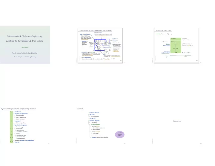
Content
– 9 – 2018-06-04 – Scontent – 5/60- Scenarios: The Idea
- Use Cases
- Use Case Diagrams
- User Stories
- Sequence Diagrams
- A Brief History
- Live Sequence Charts
- LSC Body Syntax:
- LSC Model Elements, Locations
- Well-Formedness
- Towards Semantics:
- Cuts, Firedsets
- Automaton Construction
- Excursion: Symbolic Büchi Automata
Scenarios
– 9 – 2018-06-04 – main – 6/60