Lecture 14: Architecture and Design Patterns 2015-07-02 Prof. Dr. - - PDF document

lecture 14 architecture and design patterns
SMART_READER_LITE
LIVE PREVIEW

Lecture 14: Architecture and Design Patterns 2015-07-02 Prof. Dr. - - PDF document

Softwaretechnik / Software-Engineering Lecture 14: Architecture and Design Patterns 2015-07-02 Prof. Dr. Andreas Podelski, Dr. Bernd Westphal 14 2015-07-02 main Albert-Ludwigs-Universit at Freiburg, Germany Contents of the


slide-1
SLIDE 1

– 14 – 2015-07-02 – main –

Softwaretechnik / Software-Engineering

Lecture 14: Architecture and Design Patterns

2015-07-02

  • Prof. Dr. Andreas Podelski, Dr. Bernd Westphal

Albert-Ludwigs-Universit¨ at Freiburg, Germany

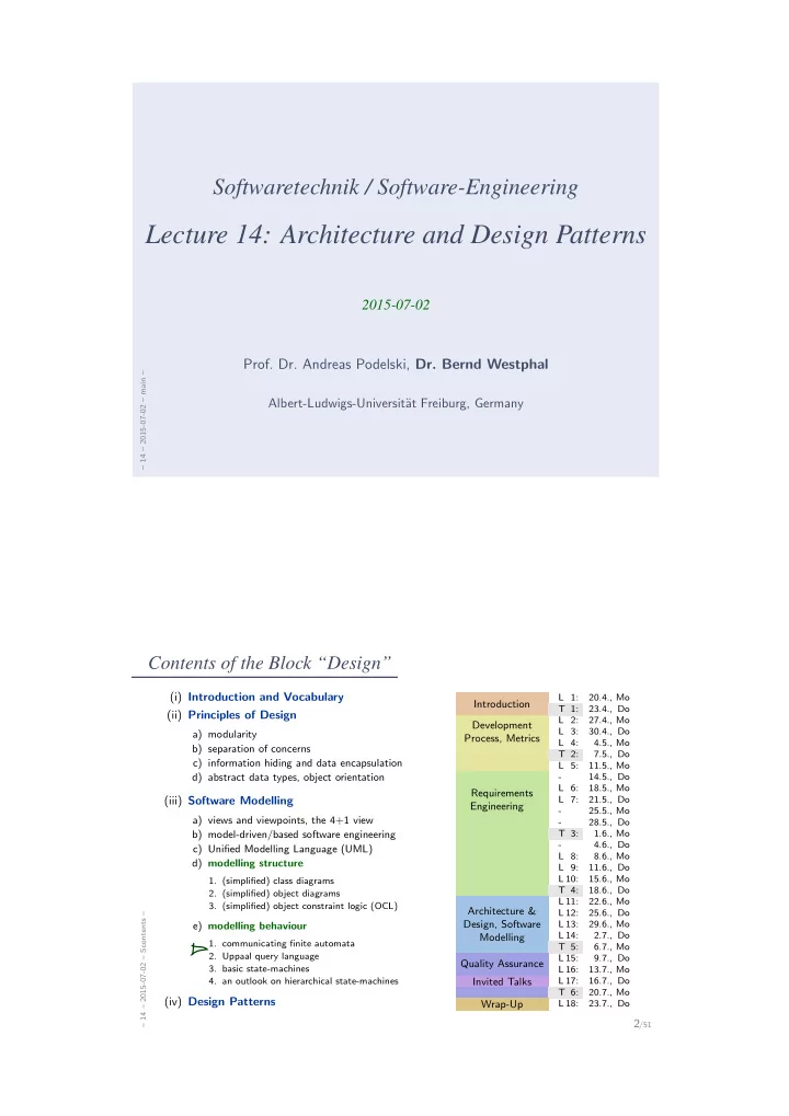
Contents of the Block “Design”

– 14 – 2015-07-02 – Scontents –

2/51 (i) Introduction and Vocabulary (ii) Principles of Design

a) modularity b) separation of concerns c) information hiding and data encapsulation d) abstract data types, object orientation

(iii) Software Modelling

a) views and viewpoints, the 4+1 view b) model-driven/based software engineering c) Unified Modelling Language (UML) d) modelling structure

  • 1. (simplified) class diagrams
  • 2. (simplified) object diagrams
  • 3. (simplified) object constraint logic (OCL)

e) modelling behaviour

  • 1. communicating finite automata
  • 2. Uppaal query language
  • 3. basic state-machines
  • 4. an outlook on hierarchical state-machines

(iv) Design Patterns

L 1: 20.4., Mo

Introduction

T 1: 23.4., Do L 2: 27.4., Mo L 3: 30.4., Do L 4: 4.5., Mo

Development Process, Metrics

T 2: 7.5., Do L 5: 11.5., Mo

  • 14.5., Do

L 6: 18.5., Mo L 7: 21.5., Do

  • 25.5., Mo
  • 28.5., Do

Requirements Engineering

T 3: 1.6., Mo

  • 4.6., Do

L 8: 8.6., Mo L 9: 11.6., Do L 10: 15.6., Mo T 4: 18.6., Do L 11: 22.6., Mo L 12: 25.6., Do L 13: 29.6., Mo L 14: 2.7., Do

Architecture & Design, Software Modelling

T 5: 6.7., Mo L 15: 9.7., Do

Quality Assurance

L 16: 13.7., Mo

Invited Talks

L 17: 16.7., Do T 6: 20.7., Mo

Wrap-Up

L 18: 23.7., Do

slide-2
SLIDE 2

Contents & Goals

– 14 – 2015-07-02 – Sprelim –

3/51

Last Lecture:

  • Networks of CFA, Tool Demo (recording will be reconstructed), Implementable CFA

This Lecture:

  • Educational Objectives: Capabilities for following tasks/questions.
  • What is the relation between greedy and standard semantics?
  • What is an Uppaal Query for, e.g., “location ℓ is reachable”?
  • What’s the difference between CFA and UML State-Machines?
  • Can each network of UML State-Machines be encoded in CFA?
  • Explain an example of an architecture (design) pattern.
  • What is “software entropy”?
  • Content:
  • Implementable CFA Cont’d
  • Uppaal Query Language
  • UML State-Machines
  • Architecture and Design Patterns (with examples)

Implementing CFA Cont’d

– 14 – 2015-07-02 – main –

4/51

slide-3
SLIDE 3

Recall: Implementable CFA

– 14 – 2015-07-02 – Simplcont –

5/51

  • Let each automaton in the network C(A1, . . . , An) be marked as

either environment or controller. We call C implementable if and only if, for each controller A in C,

(i) A is deterministic, (ii) A reads/writes only its local variables, may also read variables written by environment automata, but only in modification vectors of edges with input synchronisation, (iii) A is locally deadlock-free, i.e. enabled edges with output-actions are not blocked forever.

  • The communicating finite automaton A = (L, B, V, E, ℓini)

is called deterministic if and only if

  • for each location ℓ,
  • either all edges with ℓ as source location have pairwise different input actions,
  • or there is no edge with an input action starting at ℓ,

and all edges starting at ℓ have pairwise (logically) disjoint guards.

  • Note: implementable (i) and (ii) can be checked syntactically.

Property (iii) is a property of the whole network. Can be checked with Uppaal: (A.ℓ ∧ ϕ) − → (A.ℓ′) for each edge (ℓ, α, ϕ, r, ℓ′) of A.

Recall: Greedy CFA Semantics

– 14 – 2015-07-02 – Simplcont –

6/51

  • Greedy semantics:
  • each input synchronisation transition (plus: system start) of automaton A is followed

by a maximal sequence of internal transitions or output transitions of A.

  • Maximal: cannot be extended by an internal transition.

There may still be interleaving of the internal transitions, but (by forbidding shared variables for controllers) cannot be observed outside of an automaton. Example:

G? F! n := n + 1 E? v := v_env E! v_env > -10 v_env := v_env - 1 v_env < 10 v_env := v_env + 1 G! F? F! G!

A1: A2,1: A2,2: E:

  • A1 is implementable in C(A1, A2,1, E) (environment: only E)
  • deterministic: ✔,
  • only local variables, environment variables with input: ✔,
  • locally deadlock-free: ✔.
  • A1 is not implementable in C(A1, A2,2, E).
slide-4
SLIDE 4

Recall: Implementing CFA

– 14 – 2015-07-02 – Simplcont –

7/51

half_idle request_sent tea_selected soft_selected water_selected idle DOK? OK! water_enabled := false, soft_enabled := false, tea_enabled := false DTEA! DWATER! DSOFT! tea_enabled TEA? soft_enabled SOFT? water_enabled WATER?

st : { idle, wsel, ssel, tsel, reqs, half }; take event( E : { TAU, WATER, SOFT, TEA, ... } ) { bool stable = 1; switch (st) { case idle : switch (E) { case WATER : if (water enabled) { st := wsel; stable := 0; } ;; case SOFT : ... } case wsel: switch (E) { case TAU : send DWATER(); st := reqs; ;; } }

Model vs. Implementation

– 14 – 2015-07-02 – Simplcont –

8/51

  • Now an implementable model C(A1, . . . , An) has two semantics:
  • Cstd — standard semantics.
  • Cgrd — greedy semantics.
  • Are they related in any way? They are: Cstd ⊇ Cgrd. (∗)

Exercise: prove (∗).

  • What effect does this insight have on Uppaal verification results?
  • If there is an error in Cstd, will it be in a correct implementation (of Cgrd)?

Not necessarily.

  • If there is no error in Cstd, will a correct implementation (of Cgrd) be error-free?

Yes, definitely.

Uppaal verification shows no error reports error

  • impl. has error

yes false negative true positive no true negative false positive

slide-5
SLIDE 5

Uppaal Query Language

(Larsen et al., 1997; Behrmann et al., 2004)

– 14 – 2015-07-02 – main –

9/51

The Uppaal Query Language

– 14 – 2015-07-02 – Suppaal –

10/51

Consider N = C(A1, . . . , An) over data variables V .

  • basic formula:

atom ::= Ai.ℓ | ϕ | deadlock where ℓ ∈ Li is a location and ϕ an expression over V .

  • configuration formulae:

term ::= atom | not term | term1 and term2

  • existential path formulae:

(“exists finally”, “exists globally”) e-formula ::= ∃♦ term | ∃ term

  • universal path formulae:

(“always finally”, “always globally”, “leads to”) a-formula ::= ∀♦ term | ∀ term | term1 --> term2

  • formulae (or queries):

F ::= e-formula | a-formula

slide-6
SLIDE 6

Satisfaction of Uppaal Queries by Configurations

– 14 – 2015-07-02 – Suppaal –

11/51

  • The satisfaction relation
  • ℓ, ν |

= F between configurations

  • ℓ, ν = (ℓ1, . . . , ℓn), ν
  • f a network C(A1, . . . , An) and formulae F of the Uppaal logic

is defined inductively as follows:

ℓ, ν | = deadlock iff ℓ0,i is a dedlock configuration

ℓ, ν | = Ai.ℓ iff ℓ0,i = ℓ

ℓ, ν | = ϕ iff ν | = ϕ

ℓ, ν | = not term iff ℓ, ν | = term

ℓ, ν | = term1 and term2 iff ℓ, ν | = termi, i = 1, 2

Satisfaction of Uppaal Queries by Configurations

– 14 – 2015-07-02 – Suppaal –

12/51

Exists finally:

ℓ0, ν0 | = ∃♦ term iff ∃ path ξ of C starting in ℓ0, ν0 ∃ i ∈ N0 • ξi | = term “some configuration satisfying term is reachable” Example: ∃♦ ϕ . . . . . . . . . . . .

  • ℓ0, ν0

¬ϕ ¬ϕ ¬ϕ ¬ϕ ¬ϕ ¬ϕ ¬ϕ

λ1 λ2 λ1,1 λ2,1 λ2,2 λ2,2,1 λ2,2,2

  • ℓ, ν

ϕ

slide-7
SLIDE 7

Satisfaction of Uppaal Queries by Configurations

– 14 – 2015-07-02 – Suppaal –

13/51

Exists globally:

ℓ0, ν0 | = ∃ term iff ∃ path ξ of C starting in ℓ0, ν0 ∀ i ∈ N0 • ξi | = term “all configurations of some computation path satisfy term” Example: ∃ ϕ . . . . . . . . . . . . . . .

  • ℓ0, ν0

ϕ ¬ϕ ϕ ¬ϕ ¬ϕ ϕ ¬ϕ

λ1 λ2 λ1,1 λ2,1 λ2,2 λ2,2,1 λ2,2,2

  • ℓ, ν

ϕ

Satisfaction of Uppaal Queries by Configurations

– 14 – 2015-07-02 – Suppaal –

14/51

  • Always globally:

ℓ0, ν0 | = ∀ term iff ℓ0, ν0 | = ∃♦ ¬term

  • Always finally:

ℓ0, ν0 | = ∀♦ term iff ℓ0, ν0 | = ∃ ¬term

slide-8
SLIDE 8

Satisfaction of Uppaal Queries by Configurations

– 14 – 2015-07-02 – Suppaal –

15/51

Leads to:

ℓ0, ν0 | = term1 − → term2 iff ∀ path ξ of N starting in ℓ0, ν0 ∀ i ∈ N0 • ξi | = term1 = ⇒ ξi | = ∀♦ term2 “on all paths, from each configuration satisfying term1, a configuration satifying term2 is reachable” (response pattern) Example: ϕ1 − → ϕ2 . . . . . . . . . . . .

  • ℓ0, ν0

ϕ1, ¬ϕ2 ¬ϕ2 ϕ1, ¬ϕ2 ¬ϕ2 ϕ2 ϕ2 ϕ2 ϕ2

λ1 λ2 λ1,1 λ1,1,1 λ2,1 λ2,2 λ2,2,1 λ2,2,2

¬ϕ2

CFA Model-Checking

– 14 – 2015-07-02 – Suppaal –

16/51

  • Network satisfies query:
  • C |

= F if and only if Cini | = F.

  • Definition. The model-checking problem for a network C of commu-

nicating finite automata and a query F is to decide whether (C, F) ∈ | =.

  • Proposition. The model-checking problem for communicating finite au-

tomata is decidable.

slide-9
SLIDE 9

UML State Machines

– 14 – 2015-07-02 – main –

17/51

UML Core State Machines

– 14 – 2015-07-02 – Sumlstm –

18/51

C D

x : Int = 27 itsD 0..1 itsC 0..1

  • signal
  • E
  • signal
  • F
  • signal
  • G

s1 s2

E/itsD ! F G

s1 s2

F[x > 0]

s3

/itsC ! G /x := 0 annot ::=

  • event[ . event]∗
  • trigger

[ [ guard ] ] [ / action]

  • with
  • event ∈ E,

(optional)

  • guard ∈ Expr S

(default: true, assumed to be in Expr S )

  • action ∈ ActS

(default: skip, assumed to be in ActS )

slide-10
SLIDE 10

Event Pool and Run-To-Completion

– 14 – 2015-07-02 – Sumlstm –

19/51 s1 s2

E/itsD ! F G

s1 s2

F[x > 0]

s3

/itsC ! G /x := 0

u1 : C u2 : D x = 27

itsD itsC

u1 u2 step state stable x state stable event pool s1 1 27 s1 1 E ready for u1

Event Pool and Run-To-Completion

– 14 – 2015-07-02 – Sumlstm –

19/51 s1 s2

E/itsD ! F G

s1 s2

F[x > 0]

s3

/itsC ! G /x := 0

u1 : C u2 : D x = 27

itsD itsC

u1 u2 step state stable x state stable event pool s1 1 27 s1 1 E ready for u1 1 s2 1 27 s1 1 F ready for u2

slide-11
SLIDE 11

Event Pool and Run-To-Completion

– 14 – 2015-07-02 – Sumlstm –

19/51 s1 s2

E/itsD ! F G

s1 s2

F[x > 0]

s3

/itsC ! G /x := 0

u1 : C u2 : D x = 27

itsD itsC

u1 u2 step state stable x state stable event pool s1 1 27 s1 1 E ready for u1 1 s2 1 27 s1 1 F ready for u2 2 s2 1 27 s2 3 s2 1 27 s3 G ready for u1

Event Pool and Run-To-Completion

– 14 – 2015-07-02 – Sumlstm –

19/51 s1 s2

E/itsD ! F G

s1 s2

F[x > 0]

s3

/itsC ! G /x := 0

u1 : C u2 : D x = 27

itsD itsC

u1 u2 step state stable x state stable event pool s1 1 27 s1 1 E ready for u1 1 s2 1 27 s1 1 F ready for u2 2 s2 1 27 s2 3 s2 1 27 s3 G ready for u1 4.a s2 1 s1 1 G ready for u1 5.a s1 1 s1 1 4.b s1 1 27 s3

slide-12
SLIDE 12

Event Pool and Run-To-Completion

– 14 – 2015-07-02 – Sumlstm –

19/51 s1 s2

E/itsD ! F G

s1 s2

F[x > 0]

s3

/itsC ! G /x := 0

u1 : C u2 : D x = 27

itsD itsC

u1 u2 step state stable x state stable event pool s1 1 27 s1 1 E ready for u1 1 s2 1 27 s1 1 F ready for u2 2 s2 1 27 s2 3 s2 1 27 s3 G ready for u1 4.a s2 1 s1 1 G ready for u1 5.a s1 1 s1 1 4.b s1 1 27 s3 5.b s1 1 s1 1

Composite (or Hierarchical) States

– 14 – 2015-07-02 – Sumlstm –

20/51

  • OR-states, AND-states Harel (1987).
  • Composite states are about abbreviation, structuring, and avoiding redundancy.
  • n
  • w

e s resigned X/ n

  • w

e s resigned X/ X/ X/ X/

  • n
  • w

e s

  • slow

fast F/ F/ n fastN

  • w

fastW e fastE s fastS F/ F/

slide-13
SLIDE 13

Example

– 14 – 2015-07-02 – Sumlstm –

21/51

Idle waitOK have_c100_or_e1> have_c100 have_e1 have_c150> have_c50> drinkReady Idle waitOK have_c100_or_e1> have_c100 have_e1 have_c150> have_c50> drinkReady E1/itsChanger

  • >giveback_100()

C50/itsChoicePanel

  • >enable_Water();

E1/ itsChanger

  • >giveback_100()

C50 C50/ itsChanger

  • >giveback_50()

C50 E1/itsChoicePanel->enableSoft(); E1 C50 OK Entry Action: itsChoicePanel

  • >enable_Water();

Entry Action: itsChoicePanel

  • >enable_Soft();

Entry Action: itsChoicePanel

  • >enable_Tea();

Tea_selected Inactive Soft_selected Water_selected Request_sent Tea_selected Inactive Soft_selected Water_selected Request_sent TEA[Tea_enabled] /itsDrinkDispenser

  • >GEN(DTEA)

/itsDrinkDispenser

  • >GEN(DSOFT);

if (itsCoinValidator

  • >IS_IN(have_c150))

itsChanger->giveback_50(); WATER[Water_enabled] /disable_all(); SOFT[Soft_enabled] /itsDrinkDispenser

  • >GEN(DWATER);

if (itsCoinValidator->IS_IN(have_c150)) itsChanger->giveback_100(); else if (itsCoinValidator->IS_IN(have_c100)) itsChanger->giveback_50();

  • n
  • n

T2 Tea_out T1 T3 S2 Soft_out S1 S3 W2 Water_out W1 W3 FillingUp

  • n

T2 Tea_out T1 T3 S2 Soft_out S1 S3 W2 Water_out W1 W3 FillingUp DTEA/ Prepare_Tea(); itsCoinValidator

  • >GEN(OK);

DTEA/ Prepare_Tea(); itsCoinValidator

  • >GEN(OK);

DTEA/ Prepare_Tea(); itsCoinValidator

  • >GEN(OK);

DSOFT/ Prepare_Soft(); itsCoinValidator

  • >GEN(OK);

DSOFT/ Prepare_Soft(); itsCoinValidator

  • >GEN(OK);

DSOFT/ Prepare_Soft(); itsCoinValidator

  • >GEN(OK);

DWATER/ Prepare_Water(); itsCoinValidator

  • >GEN(OK);

DWATER/ Prepare_Water(); itsCoinValidator

  • >GEN(OK);

DWATER/ Prepare_Water(); itsCoinValidator

  • >GEN(OK);

FILLUP/itsCoinValidator

  • >update_ChoicePanel();

Would be Too Easy. . .

– 14 – 2015-07-02 – Sumlstm –

22/51

  • s1

s2

  • s3

s8 s4

  • s5

s6

E/ F/ F/ E/ G/

s7 [true]/ F/ → “Software Design, Modelling, and Analysis with UML” in the winter semester.

slide-14
SLIDE 14

Rhapsody Architecture

– 14 – 2015-07-02 – Sumlstm –

23/51

UML Modes

– 14 – 2015-07-02 – main –

24/51

slide-15
SLIDE 15

UML and the Pragmatic Attribute

– 14 – 2015-07-02 – Sumlmode –

25/51

Recall: definition “model” (Glinz, 2008, 425): [...] (iii) the pragmatic attribute, i.e. the model is built in a specific context for a specific purpose. Examples for context/purpose: Floorplan as sketch: Floorplan as blueprint: Floorplan as program: +

wiringplan

+

windows

+

...

With UML it’s the Same [http://martinfowler.com/bliki]

– 14 – 2015-07-02 – Sumlmode –

26/51

The last slide is inspired by Martin Fowler, who puts it like this: “[...] people differ about what should be in the UML because there are differing fundamental views about what the UML should be. I came up with three primary classifications for thinking about the UML: UmlAsSketch, UmlAsBlueprint, and UmlAsProgrammingLanguage. ([...] S. Mellor independently came up with the same classifications.) So when someone else’s view of the UML seems rather different to yours, it may be because they use a different UmlMode to you.” Claim:

  • This not only applies to UML as a language (what should be in it etc.?),
  • but at least as well to each individual UML model.
slide-16
SLIDE 16

With UML it’s the Same [http://martinfowler.com/bliki]

– 14 – 2015-07-02 – Sumlmode –

26/51

The last slide is inspired by Martin Fowler, who puts it like this: “[...] people differ about what should be in the UML because there are differing fundamental views about what the UML should be. I came up with three primary classifications for thinking about the UML: UmlAsSketch, UmlAsBlueprint, and UmlAsProgrammingLanguage. ([...] S. Mellor independently came up with the same classifications.) So when someone else’s view of the UML seems rather different to yours, it may be because they use a different UmlMode to you.” Claim:

  • This not only applies to UML as a language (what should be in it etc.?),
  • but at least as well to each individual UML model.

Sketch In this UmlMode developers use the UML to help communicate some aspects of a system. [...] Sketches are also useful in documents, in which case the focus is communication ra- ther than completeness. [...] The tools used for sketching are lightweight drawing tools and often people aren’t too particular about keeping to every strict rule of the UML. Most UML diagrams shown in books, such as mine, are sketches. Their emphasis is on selective communication rather than complete specification. Hence my sound-bite “com- prehensiveness is the enemy

  • f comprehensibility”

Blueprint [...] In forward engineering the idea is that blueprints are developed by a designer whose job is to build a detailed design for a programmer to code up. That design should be sufficiently complete that all design decisions are laid

  • ut and the programming

should follow as a pretty straightforward activity that requires little thought. [...] Blueprints require much more sophisticated tools than sketches in order to handle the details required for the task. [...] Forward engineering tools support diagram drawing and back it up with a repos- itory to hold the informa-

  • tion. [...]

ProgrammingLanguage If you can detail the UML enough, and provide semantics for everything you need in software, you can make the UML be your programming language. Tools can take the UML diagrams you draw and compile them into executable code. The promise of this is that UML is a higher level language and thus more productive than current programming languages. The question, of course, is whether this promise is true. I don’t believe that graph- ical programming will succeed just because it’s

  • graphical. [...]

UML-Mode of the Lecture: As Blueprint

– 14 – 2015-07-02 – Sumlmode –

27/51

  • The “mode” fitting the lecture best is AsBlueprint.

Goal:

  • be precise to avoid misunderstandings.
  • allow formal analysis of consistency/implication
  • n the design level — find errors early.

Yet we tried to be consistent with the (informal semantics) from the standard documents OMG (2007a,b) as far as possible.

Plus:

  • Being precise also helps to work in mode AsSketch:

Knowing “the real thing” should make it easier to (i) “see” which blueprint(s) the sketch is supposed to denote, and (ii) to ask meaningful questions to resolve ambiguities.

slide-17
SLIDE 17

Architecture Patterns

– 14 – 2015-07-02 – main –

28/51

Introduction

– 14 – 2015-07-02 – Sarch –

29/51

  • Over decades of software engineering, many clever, proved and tested designs of solutions

for particular problems emerged.

  • Question: can we generalise, document and re-use these designs?
  • Goal: “don’t re-invent the wheel” / benefit from “clever”, “proven and tested”, “solution”.

architectural pattern — An architectural pattern expresses a fundamental structural organization schema for software systems. It provides a set of prede- fined subsystems, specifies their responsibilities, and includes rules and guide- lines for organizing the relationships between them.

Buschmann et al. (1996)

  • Using an architectural pattern
  • implies certain characteristics or properties of the software (construction, extendibility,

communication, dependencies, etc.),

  • determines structures on a high level of the architecture, thus is typically a central and

fundamental design decision.

  • The information that (where, how, . . . ) a well-known architecture / design pattern is

used in a given software can make comprehension and maintenance significantly easier.

slide-18
SLIDE 18

Example: Layered Architectures

– 14 – 2015-07-02 – Sarch –

30/51

  • (Z¨

ullighoven, 2005):

  • A layer whose components only interact with components of their direct neighbour

layers is called protocol-based layer. A protocol-based layer hides all layers beneath it and defines a protocol which is (only) used by the layers directly above.

  • Example: The ISO/OSI reference model.
  • 7. Application
  • 6. Presentation
  • 5. Session
  • 4. Transport
  • 3. Network
  • 2. Data link
  • 1. Physical
  • 7. Application
  • 6. Presentation
  • 5. Session
  • 4. Transport
  • 3. Network
  • 2. Data link
  • 1. Physical

data packets frames bits

Example: Layered Architectures Cont’d

– 14 – 2015-07-02 – Sarch –

31/51

  • object-oriented layer: interacts with layers directly and possibly further above and below.
  • Rules: the components of a layer may use
  • only components of the protocol-based layer directly beneath,
  • all components of layers further beneath.

GNOME etc. Applications GTK+ GDK ATK Cairo GLib GIO Pango

slide-19
SLIDE 19

Example: Layered Architectures Cont’d

– 14 – 2015-07-02 – Sarch –

31/51

  • object-oriented layer: interacts with layers directly and possibly further above and below.
  • Rules: the components of a layer may use
  • only components of the protocol-based layer directly beneath,
  • all components of layers further beneath.

GNOME etc. Applications GTK+ GDK ATK Cairo GLib GIO Pango

Example: Three-Tier Architecture

– 14 – 2015-07-02 – Sarch –

32/51

Desktop Host

presentation tier

Application Server

(business) logic tier data tier

Database Server

DBMS (Ludewig and Lichter, 2013)

  • presentation layer:

user interface; presents information obtained from the logic layer to the user, controls inter- action with the user, i.e. requests actions at the logic layer according to user inputs,

  • logic layer:

core system functionality; layer is designed with-

  • ut information about the presentation layer,

may only read/write data according to data layer interface

  • data layer:

persistent data storage; hides information about how data is organised, read, and written, offers particular chunks of information in a form useful for the logic layer.

  • Examples: Web-shop, business software (enterprise resource planning), etc.
slide-20
SLIDE 20

Layered Architectures: Discussion

– 14 – 2015-07-02 – Sarch –

33/51

  • Advantages:
  • protocol-based: only neighouring layers are coupled, i.e. components of these layers

interact,

  • coupling is low, data usually encapsulated,
  • changes have local effect (only neighbouring layers affected),
  • protocol-based: distributed implementation often easy.
  • Disadvantages:
  • performance (as usual), nowadays often not a problem.

Example: Pipe-Filter

– 14 – 2015-07-02 – Sarch –

34/51

Example: Compiler

lexical analysis (lexer) syntactical analysis (parser) semantical analysis code generation ASCII Tokens AST dAST

Sourcecode Objectcode Errormessages

Example: UNIX Pipes ls -l | grep Sarch.tex | awk ’{ print $5 }’

  • Disadvantages:
  • if the filters use a common data exchange format, all filters may need changes if the

format is changed, or need to employ (costly) conversions.

  • filters do not use global data, in particular not to handle error conditions.
slide-21
SLIDE 21

Example: Model-View-Controller

– 14 – 2015-07-02 – Sarch –

35/51

controller view model

sees uses change of visualisation manipulation

  • f data

notification of updates access to data

https://commons.wikimedia.org/wiki/File:Maschinenleitstand KWZ.jpg Dergenaue, CC-BY-SA-2.5

Example: Model-View-Controller

– 14 – 2015-07-02 – Sarch –

35/51

controller view model

sees uses change of visualisation manipulation

  • f data

notification of updates access to data

https://commons.wikimedia.org/wiki/File:Maschinenleitstand KWZ.jpg Dergenaue, CC-BY-SA-2.5

  • Advantages:
  • one model can serve multiple view/controller pairs;
  • view/controller pairs can be

added and removed at runtime;

  • model visualisation always

up-to-date in all views;

  • distributed implementation (more or less) easily.
  • Disadvantages:
  • if the view needs a lot of data, updating the view can be inefficient.
slide-22
SLIDE 22

Design Patterns

– 14 – 2015-07-02 – main –

36/51

Design Patterns

– 14 – 2015-07-02 – Sdespat –

37/51

  • In a sense the same as architectural patterns, but on a lower scale.
  • Often traced back to (Alexander et al., 1977; Alexander, 1979).

Design patterns ... are descriptions of communicating objects and classes that are cus- tomized to solve a general design problem in a particular context. A design pattern names, abstracts, and identifies the key aspects of a common design structure that make it useful for creating a reusable object-oriented design. (Gamma et al., 1995)

slide-23
SLIDE 23

Example: Strategy

– 14 – 2015-07-02 – Sdespat –

38/51 Strategy Problem The only difference between similar classes is that they solve the same problem by different algorithms. Solution

  • Have one class StrategyContext with all common operations.
  • Another class Strategy provides signatures for all operations to be

implemented differently.

  • From Strategy derive one sub-class ConcreteStrategy for each

implementation alternative.

  • StrategyContext uses concrete Strategy-objects to execute the

different implementations via delegation.

Structure

StrategyContext

+ contextInterface()

Strategy

+ algorithm()

ConcreteStrategy1

+ algorithm()

ConcreteStrategy2

+ algorithm()

Example: Pattern Usage and Documentation

– 14 – 2015-07-02 – Sdespat –

39/51

Painter SimpleUpdateStrategy DrawingView Tool DrawingEditor CreationTool SelectionTool Drawing Figure

Strategy: Strategy Strategy: ConcreteStrategy Strategy: ConcreteContext Observer: Observer Mediator: Colleague State: StateContext Mediator: Colleague State: State Mediator: Mediator State: ConcreteState State: ConcreteState Observer: Subject Mediator: Colleague

Pattern usage in JHotDraw framework (JHotDraw, 2007) (Diagram: (Ludewig and Lichter, 2013))

slide-24
SLIDE 24

Example: Singleton and Memento

– 14 – 2015-07-02 – Sdespat –

40/51 Singleton Problem Of one class, exactly one instance should exist in the system. Example Print spooler. Memento Problem The state of an object needs to be archived in a way that allows to re-construct this state without violating the principle of data encapsulation. Example Undo mechanism.

Example: Mediator, Observer, and State

– 14 – 2015-07-02 – Sdespat –

41/51

Mediator Problem Objects interacting in a complex way should only be loosely coupled and be easily exchangeable. Example Appearance and state of different means of interaction (menus, buttons, input fields) in a graphical user interface (GUI) should be consistent in each interaction state. Observer Problem Multiple objects need to adjust their state if one particular other

  • bject is changed.

Example All GUI object displaying a file system need to change if files are added or removed. State Problem The behaviour of an object depends on its (internal) state. Example The effect of pressing the room ventilation button depends (among

  • thers?) on whether the ventilation is on or off.
slide-25
SLIDE 25

Meta Design Pattern: Inversion of Control

– 14 – 2015-07-02 – Sdespat –

42/51

  • “don’t call us, we’ll call you”
  • Classical (small) embedded controller software:
  • while (true) {

// read inputs // compute updates // write outputs }

  • User interfaces, for example:
  • define button callback();
  • register method with UI-framework (→ later),
  • whenever button is pressed (handled by UI-framework),

button callback() is called and does its magic.

  • Also found in MVC and observer patterns:

model notifies view, subject notifies observer.

Design Patterns: Discussion

– 14 – 2015-07-02 – Sdespat –

43/51

  • “The development of design patterns is considered to be one of the most important

innovations of software engineering in recent years.” (Ludewig and Lichter, 2013)

  • Advantages:
  • (Re-)use the experience of others and employ well-proven solutions.
  • Can improve on quality criteria like changeability or re-use.
  • Provide a vocabulary for the design process, thus facilitates documentation of

architectures and discussions about architecture.

  • Can be combined in a flexible way, one class in a particular architecture can correspond

to roles of multiple patterns.

  • Helps teaching software design.
  • Disadvantages:
  • Using a pattern is not a value as such — using too much global data cannot be

justified by “but it’s the pattern Singleton”.

  • Again: reading is easy, writing need not be.

Here: Understanding abstract descriptions of design patterns or their use in existing software may be easy — using design patterns appropriately in new designs requires (surprise, surprise) experience.

slide-26
SLIDE 26

Libraries and Frameworks

– 14 – 2015-07-02 – Sdespat –

44/51

  • (Class) Library: a collection of operations or classes offering generally usable functionality

in a re-usable way. Examples:

  • libc — standard C library (is in particular abstraction layer for operating system functions),
  • GMP — GNU multi-precision library, cf. Lecture 6.
  • libz — compress data.
  • libxml — read (and validate) XML file, provide DOM tree.
  • Framework: an architecture consists of class hierarchies which determine a generic

solution for similar problems in a particular context.

  • Example: Android Application Framework

http://developer.android.com/training/basics/activity-lifecycle/starting.html

slide-27
SLIDE 27

Libraries and Frameworks

– 14 – 2015-07-02 – Sdespat –

44/51

  • (Class) Library: a collection of operations or classes offering generally usable functionality

in a re-usable way. Examples:

  • libc — standard C library (is in particular abstraction layer for operating system functions),
  • GMP — GNU multi-precision library, cf. Lecture 6.
  • libz — compress data.
  • libxml — read (and validate) XML file, provide DOM tree.
  • Framework: an architecture consists of class hierarchies which determine a generic

solution for similar problems in a particular context.

  • Example: Android Application Framework
  • The difference lies in flow-of-control:

library modules are called from user code, frameworks call user code.

  • Product line: parameterised design/code

(“all turn indicators are equal, turn indicators in premium cars are more equal”).

  • For some application domains, there are reference architectures (games, compilers).

Reference Architecture Example: Games

– 14 – 2015-07-02 – Sdespat –

45/51

Tron Joystick? . . . Keyboard? Control Player colour score direction speed Gameplay Render OpenGL? . . . aalib? AI? Segment x0, y0 x1, y1 colour Engine areawidth areaheight

1..∗ notify update 0..∗ head world 1..∗

Main External inputs

  • Keyboard
  • Joystick
  • . . .

Game Logic

  • player scores
  • interface inputs/engine

(Physics) Engine

  • physical objects
  • collision notification

Output

  • Graphics

(from ASCII to bitmap; native or via API)

  • Sound
  • . . .

notify update ? ?

slide-28
SLIDE 28

Quality Criteria on Architectures

– 14 – 2015-07-02 – Sdesq –

46/51

  • testability
  • architecture design should keep testing (or formal verification) in mind (buzzword “design for

verification”),

  • high locality of design units may make testing significantly easier (module testing),
  • particular testing interfaces may improve testability (e.g. allow injection of user input not only

via GUI, or provide particular log output for tests).

  • changeability, maintainability
  • most systems that are used need to be changed or maintained, in particular when requirements

change,

  • risk assessment: parts of the system with high probability for changes should be designed such

that changes are possible with acceptable effort (abstract, modularise, encapsulate),

  • portability
  • systems with a long lifetime may need to be adapted to different platforms over time,

infrastructure like databases may change,

  • porting: adaptation to different platform (OS, hardware, infrastructure).
  • Note: a good design (model) is first of all supposed to support the solution,

it need not be a good domain model.

Software Entropy

– 14 – 2015-07-02 – Sdesq –

47/51

  • Lehman’s Laws of Software Evolution (Lehman and Belady, 1985):

(i) A program that is used will be modified. (ii) When a program is modified, its complexity will increase, provided that one does not actively work against this.

  • Software entropy E (measure of disorder) Jacobson et al. (1992)

claim: ∆E ∼ E

  • “when designing a system with the intention of it being maintainable, we try to give it

the lowest software entropy possible from the beginning.”

  • Work against disorder: re-factoring

(re-assign data and operations to modules, introduce new layers generalising old and new solutions, (automatically) check that intended interfaces are not bypassed, etc.)

  • Proposal (Jacobson et al., 1992):
  • use “probability for change” as

guideline in (architecture) design,

  • i.e. base design on a thorough analysis
  • f problem and solution domain.

item probability for change Object from application [domain] Low Long-lived information structures Low Passive object’s attribute Medium Sequences of behaviour Medium Interface with outside world High Functionality High

slide-29
SLIDE 29

Development Approaches

– 14 – 2015-07-02 – Sdesq –

48/51 task, problem

  • utside-in

inside-out top-down bottom-up

user interface system software, hardware

  • top-down risk: needed functionality hard to realise on target platform.
  • bottom-up risk: lower-level units do not “fit together”.
  • inside-out risk: user interface needed by customer hard to realise with existing system,
  • outside-in risk: elegant system design not reflected nicely in (already fixed) UI.
slide-30
SLIDE 30

References

– 14 – 2015-07-02 – main –

50/51

References

– 14 – 2015-07-02 – main –

51/51

Alexander, C. (1979). The Timeless Way of Building. Oxford University Press. Alexander, C., Ishikawa, S., and Silverstein, M. (1977). A Pattern Language – Towns, Buildings, Construction. Oxford University Press. Behrmann, G., David, A., and Larsen, K. G. (2004). A tutorial on uppaal 2004-11-17. Technical report, Aalborg University, Denmark. Buschmann, F., Meunier, R., Rohnert, H., Sommerlad, E., and Stal, M. (1996). Pattern-Oriented Software Architecture – A System of

  • Patterns. John Wiley & Sons.

Gamma, E., Helm, R., Johnsson, R., and Vlissides, J. (1995). Design Patterns – Elements of Reusable Object-Oriented Software. Addison-Wesley. Glinz, M. (2008). Modellierung in der Lehre an Hochschulen: Thesen und Erfahrungen. Informatik Spektrum, 31(5):425–434. Harel, D. (1987). Statecharts: A visual formalism for complex systems. Science of Computer Programming, 8(3):231–274. Jacobson, I., Christerson, M., and Jonsson, P. (1992). Object-Oriented Software Engineering - A Use Case Driven Approach. Addison-Wesley. JHotDraw (2007). http://www.jhotdraw.org. Larsen, K. G., Pettersson, P., and Yi, W. (1997). Uppaal in a nutshell. International Journal on Software Tools for Technology Transfer, 1(1):134–152. Lehman, M. M. and Belady, L. (1985). Program Evolution. Process of Software Change. Academic Press. Ludewig, J. and Lichter, H. (2013). Software Engineering. dpunkt.verlag, 3. edition. OMG (2007a). Unified modeling language: Infrastructure, version 2.1.2. Technical Report formal/07-11-04. OMG (2007b). Unified modeling language: Superstructure, version 2.1.2. Technical Report formal/07-11-02. Z¨ ullighoven, H. (2005). Object-Oriented Construction Handbook - Developing Application-Oriented Software with the Tools and Materials

  • Approach. dpunkt.verlag/Morgan Kaufmann.