laser straight
play

(laser straight) Central MDI & Interaction 1 -Introduction - PowerPoint PPT Presentation

Tunnel implementations (laser straight) Central MDI & Interaction 1 -Introduction -Feasibility Studies -CDR status -Implementation issues -Plans 2012-16 -Conclusions Several others in the process of World-wide


  1. Tunnel implementations (laser straight) Central MDI & Interaction 1 -Introduction -Feasibility Studies -CDR status -Implementation issues -Plans 2012-16 -Conclusions

  2. Several others in the process of World-wide CLIC&CTF3 Collaboration being added or being linked to the CLIC efforts through common technical developments CLIC multi-lateral collaboration - 43 Institutes from 22 countries ACAS (Australia) Gazi Universities (Turkey) John Adams Institute/RHUL (UK) PSI (Switzerland) Aarhus University (Denmark) Helsinki Institute of Physics (Finland) JINR (Russia) RAL (UK) Ankara University (Turkey) IAP (Russia) Karlsruhe University (Germany) RRCAT / Indore (India) Argonne National Laboratory (USA) IAP NASU (Ukraine) KEK (Japan) SLAC (USA) Athens University (Greece) IHEP (China) LAL / Orsay (France) Sincrotrone Trieste/ELETTRA (Italy) BINP (Russia) INFN / LNF (Italy) LAPP / ESIA (France) Thrace University (Greece) CERN Instituto de Fisica Corpuscular (Spain) NIKHEF/Amsterdam (Netherland) Tsinghua University (China) CIEMAT (Spain) IRFU / Saclay (France) NCP (Pakistan) University of Oslo (Norway) Cockcroft Institute (UK) Jefferson Lab (USA) North-West. Univ. Illinois (USA) Uppsala University (Sweden) ETH Zurich (Switzerland) John Adams Institute/Oxford (UK) Patras University (Greece) UCSC SCIPP (USA) FNAL (USA) Joint Institute for Power and Nuclear Research Polytech. Univ. of Catalonia (Spain) SOSNY /Minsk (Belarus)

  3. CLIC physics potential CLIC physics potential is complementary to LHC Beyond LHC discovery reach: • e+e- collisions give access to additional physics processes weakly interacting states (e.g. slepton, chargino, neutralino searches) • • more clean conditions than in LHC • Defined initial state + more precise measurements σ (fb) Examples highlighted in the CDR Higgs physics (SM and non-SM) • • Top SUSY • • Higgs strong interactions New Z’ sector • Contact interactions • • Extra dimensions …. • √s ( GeV) Lucie Linssen, CLIC CDR, SPC meeting 13 Dec 2011 3

  4. CLIC implementation – in stages? CLIC two-beam scheme compatible with energy staging to Linac 1 I.P. Linac 2 provide the optimal machine for a large energy range 0.5 TeV Stage Injector Complex Lower energy machine can run most of the time during the 4 km 4 km construction of the next stage. ~14 km Physics results will determine the energies of the stages Linac 1 I.P. Linac 2 1-2 TeV Stage Injector Complex 7.0-14 km 7.0-14 km ~20-34 km Linac 1 I.P. Linac 2 3 TeV Stage Injector Complex 3 km 3 km 20.8 km 20.8 km 48.2 km -Introduction -Feasibility Studies -CDR status -Implementation issues -Plans 2012-16 -Conclusions 4

  5. Consequences of a staged approach Physics - how do we build the Construction scenario (and approval optimal machine given a physics scenario): scenario (partly seen at LHC ?): Explore how we in practice will do Understand the benefits of running the tunneling and close to thresholds versus at productions/installation/movement highest energy, and distribution of of parts in a multistage approach ? luminosities as function of energy Power and energy development. Costs - Initial machine plus energy Have started to work on energy upgrade: External cost review 21- estimates (not only max power at 22.2.2012, costs will be discussed in max luminosity and the highest volume 3 of the CDR energy) based on running scenarios and power on/off/standby estimates (next two slides) Timescale/lifecycle for project re-defined: Buildup of drive beam (CLIC zero), stages one – physics, more stages/extensions Parameters: energy steps and scans, inst. and int. luminosities, commissioning and lum. ramp up times. -Introduction -Feasibility Studies -CDR status -Implementation issues -Plans 2012-16 -Conclusions 5

  6. A possible energy/luminosity scenario With a model (see figure for one example) for energies and luminosities, and assumptions about running scenarios (see below), one can extract power and energy estimates as function of time (next slide). For each value of CM energy: - 177 days/year of beam time - 188 days/year of scheduled and fault stops - First year - 59 days of injector and one-by-one sector commissioning - 59 days of main linac commissioning, one linac at a time - 59 days of luminosity operation - Quoted power : average over the three periods - All along : 50% of downtime - Second year - 88 days with one linac at a time and 30 % of downtime - 88 days without downtime - Quoted power : average over the two periods - Third year - Still only one e+ target at 0.5 TeV, like for years 1 & 2 - Nominal at 1.5 and 3 TeV - Power during stops (scheduled, fault, downtime) : - (40 MW, 45 MW, 60 MW) at (0.5, 1.5, 3) TeV, -Introduction -Feasibility Studies -CDR status -Implementation issues -Plans 2012-16 -Conclusions 6 respectively

  7. Power/energy Other models can be envisaged (this is one out of many), and one should also keep in mind that reducing the instantaneous luminosity at the highest energies reduced both power and yearly energy, and finer energy scans might well be needed within one stage The possible « economy » (see blue curves): Sobriety Reduced current density in normal-conducting magnets Reduction of heat loads to HVAC Re-optimization of accelerating gradient with different objective function Efficiency Grid-to-RF power conversion Permanent or super-ferric superconducting magnets Energy management Low-power configurations in case of beam interruption Modulation of scheduled operation to match electricity demand: Seasonal and Diurnal Waste heat recovery Possibilities of heat rejection at higher temperature Waste heat valorization by concomitant needs, e.g. residential heating, absorption cooling -Introduction -Feasibility Studies -CDR status -Implementation issues -Plans 2012-16 -Conclusions 7

  8. CLIC project time-line From 2016 – Project Implementation phase, including an initial project to lay the grounds for full construction: • CLIC 0 – a significant part of the drive beam facility: prototypes of hardware components at real frequency, final validation of drive beam quality/main beam emittance preservation, facility for reception tests – and part of the final project) • Finalization of the CLIC technical design, taking into account the results of Final CLIC CDR and technical studies done in the previous phase, and final energy staging scenario feasibility established, based on the LHC Physics results, which should be fully available by the time also input for the Eur. • Further industrialization and pre-series production of large series components Strategy Update with validation facilities 2004 - 2012 2012 - 2016 ~ 2020 onwards 2016 - 2020 2011-2016 – Goal: Develop a project implementation plan for a Linear Collider: CLIC project construction – • Addressing the key physics goals as emerging from the LHC data in stages, making use of • With a well-defined scope (i.e. technical implementation and operation model, CLIC 0 energy and luminosity), cost and schedule • With a solid technical basis for the key elements of the machine and detector • 
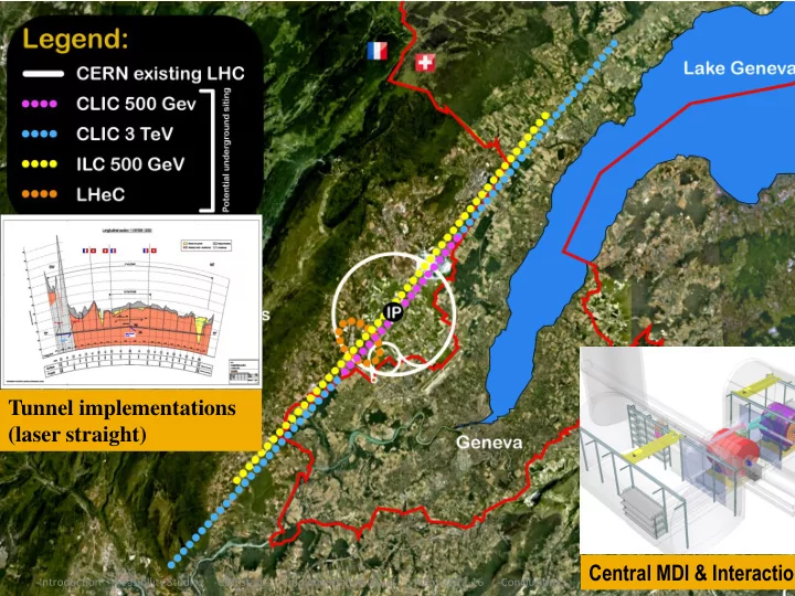
Including the necessary preparation for siting the machine • Within a project governance structure as defined with international partners -Introduction -Feasibility Studies -CDR status -Implementation issues -Plans 2012-16 -Conclusions 8

  9. The objectives and plans for 2012-16 In order to achieve the overall goal for 2016 the follow four primary objectives for 2011 — 16 can defined: • These are to be addressed by activities (studies, working groups, task forces) or work-packages (technical developments, prototyping and tests of single components or larger systems at various places) Define the scope, strategy and cost of the project implementation. Main input: The evolution of the physics findings at LHC and other relevant data Findings from the CDR and further studies, in particular concerning minimization of the technical risks, cost, power as well as the site implementation. A Governance Model as developed with partners. Define and keep an up-to-date optimized overall baseline design that can achieve the scope within a reasonable schedule, budget and risk. Beyond beam line design, the energy and luminosity of the machine, key studies will address stability and alignment, timing and phasing, stray fields and dynamic vacuum including collective effects. Other studies will address failure modes and operation issues. -Introduction -Feasibility Studies -CDR status -Implementation issues -Plans 2012-16 -Conclusions 9

Download Presentation
Download Policy: The content available on the website is offered to you 'AS IS' for your personal information and use only. It cannot be commercialized, licensed, or distributed on other websites without prior consent from the author. To download a presentation, simply click this link. If you encounter any difficulties during the download process, it's possible that the publisher has removed the file from their server.

Recommend


More recommend