
SLIDE 1
Kraft Power is the North America Master Distributor for Transfluid - - PowerPoint PPT Presentation
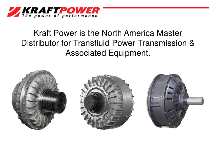
Kraft Power is the North America Master Distributor for Transfluid Power Transmission & Associated Equipment. A fluid coupling is a hydrokinetic transmission that performs like a centrifugal pump and a hydraulic turbine. 52 + Years Its
The input drive (e.g. electric motor or Diesel engine) is connected to the pump/ impeller. The wear is practically zero since there are no mechanical
difference (slip) between pump and turbine, I.E. Fluid Level. slip %=((input speed - out speed) / input speed) x 100 M echanical energy is conveyed via the pump/ impeller to the oil in the coupling The oil moves by centrifugal force across the blades of the turbine towards the outside of the coupling. The turbine absorbs the kinetic energy and develops a torque which is always equal to input torque, thus causing rotation of the output shaft.
Mm = Starting Torque of the Electric Motor MI = Transmitted Torque from Fluid Coupling Mn = Nominal Torque at Fluid Load …… Accelerating Torque
Electronics must be installed in a controlled environment and are susceptible to environmental conditions. Fluid Couplings excel in dirt, hot, humid, wet and dusty locations. Electronic devices react to power supplied, over/under voltage, lightening, blackout and harmonics. Fluid Couplings are independent, they are unaffected by power supplied. Electronic devices usually require specially wound motors. Fluid Couplings will use any motor. Electronic devices have a manufacturing life cycle of 7 years, 7 years for parts. Fluid Couplings have barely changed in the past fifty years. Electronic are extremely difficult to repair and require highly priced technician to repair . Fluid Couplings are simple to repair and it can be done at most well equipped shops. Drives designed with electronics, rigid and unforgiving to jams and shocks. The super elastic effect of a fluid coupling prevents equipment damage from shocks, jams and overload.
High efficiency, Minimum maintenance Very smooth start-ups Reduction of motor current absorptions during the starting phase: the motor starts with low load. Protection of the drive line from jams, overloads and vibrations increasing the drive-line life. Use asynchronous squirrel cage motors instead of special motors for soft-starter or inverter devices. Limited starting torque even below electric motor nominal torque. Possibility to achieve a high number of starts. Load balancing with multiple motor drive: fluid couplings easily adjust load speed to the motor speed. Load balancing in case of a multiple motor drive: fluid couplings easily adjust load speed to the motor speed
What do we need to size the Fluid Coupling? Best with
The minimum is
Better with
KX has a fusible plug that in case of intervention, releases the oil from the working circuit to a tank preventing oil leakage into the ambient The bearings are greased for life and additionally protected by two double seals Instead of oil, the coupling can work using treated water upon request - Water/ glycole mixture KX fluid couplings with ATEX rules for gas and dust explosion protection 30HP - 1,600HP 1,000 RPM - 1,800 RPM
Transfluid designed the KTB series variable fill fluid coupling to overcome difficulties experienced during ‘start up’ and ‘speed variation’ operation for medium or high powered machines, driven by electric motors or internal combustion engines.
Transfluid designed the KSL series variable fill fluid coupling to overcome difficulties experienced during ‘start up’ and ‘speed variation’ operation for medium or high powered machines, driven by electric motors or internal combustion engines.
SKF FLUID COUPLING FOR INTERNAL COM BUSTION ENGINES UP 180HP KPT FLUID COUPLING FOR INTERNAL COM BUSTION ENGINES UP 1,500HP REM OTE START & STOPS
M ulti Pump Drive Designed to “sandwich” between and engine and a PTO or Transmission , SAE standard Drives Pulleys, Pumps, ETC Hydraulic or Air Actuated Power Take-off Powers up to 1,100 HP Remote engagement RBD Elastic Coupling Designed for use with industrial engines in stationary applications such as generators, pumps, and compressor sets.