KERMA and DPA tallies in the Monte Carlo code MCS Matthieu Lemaire, - - PDF document

β–Ά
kerma and dpa tallies in the monte carlo code mcs
SMART_READER_LITE
LIVE PREVIEW

KERMA and DPA tallies in the Monte Carlo code MCS Matthieu Lemaire, - - PDF document

Transactions of the Korean Nuclear Society Virtual Spring Meeting July 9-10, 2020 KERMA and DPA tallies in the Monte Carlo code MCS Matthieu Lemaire, Hyunsuk Lee, Deokjung Lee* Department of Nuclear Engineering, Ulsan National Institute of


slide-1
SLIDE 1

KERMA and DPA tallies in the Monte Carlo code MCS

Matthieu Lemaire, Hyunsuk Lee, Deokjung Lee* Department of Nuclear Engineering, Ulsan National Institute of Science and Technology, 50 UNIST-gil, Ulsan, 44919, Republic of Korea

*Corresponding author: deokjung@unist.ac.kr

  • 1. Introduction

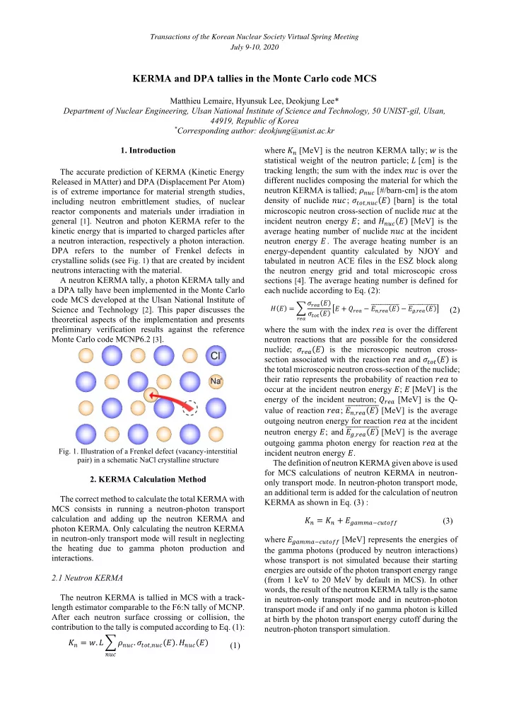
The accurate prediction of KERMA (Kinetic Energy Released in MAtter) and DPA (Displacement Per Atom) is of extreme importance for material strength studies, including neutron embrittlement studies, of nuclear reactor components and materials under irradiation in general [1]. Neutron and photon KERMA refer to the kinetic energy that is imparted to charged particles after a neutron interaction, respectively a photon interaction. DPA refers to the number of Frenkel defects in crystalline solids (see Fig. 1) that are created by incident neutrons interacting with the material. A neutron KERMA tally, a photon KERMA tally and a DPA tally have been implemented in the Monte Carlo code MCS developed at the Ulsan National Institute of Science and Technology [2]. This paper discusses the theoretical aspects of the implementation and presents preliminary verification results against the reference Monte Carlo code MCNP6.2 [3].

  • Fig. 1. Illustration of a Frenkel defect (vacancy-interstitial

pair) in a schematic NaCl crystalline structure

  • 2. KERMA Calculation Method

The correct method to calculate the total KERMA with MCS consists in running a neutron-photon transport calculation and adding up the neutron KERMA and photon KERMA. Only calculating the neutron KERMA in neutron-only transport mode will result in neglecting the heating due to gamma photon production and interactions. 2.1 Neutron KERMA The neutron KERMA is tallied in MCS with a track- length estimator comparable to the F6:N tally of MCNP. After each neutron surface crossing or collision, the contribution to the tally is computed according to Eq. (1): πΏπ‘œ = π‘₯. 𝑀 βˆ‘ πœπ‘œπ‘£π‘‘. πœπ‘’π‘π‘’,π‘œπ‘£π‘‘(𝐹). πΌπ‘œπ‘£π‘‘(𝐹)

π‘œπ‘£π‘‘

(1) where πΏπ‘œ [MeV] is the neutron KERMA tally; π‘₯ is the statistical weight of the neutron particle; 𝑀 [cm] is the tracking length; the sum with the index π‘œπ‘£π‘‘ is over the different nuclides composing the material for which the neutron KERMA is tallied; πœπ‘œπ‘£π‘‘ [#/barn-cm] is the atom density of nuclide π‘œπ‘£π‘‘; πœπ‘’π‘π‘’,π‘œπ‘£π‘‘(𝐹) [barn] is the total microscopic neutron cross-section of nuclide π‘œπ‘£π‘‘ at the incident neutron energy 𝐹; and πΌπ‘œπ‘£π‘‘(𝐹) [MeV] is the average heating number of nuclide π‘œπ‘£π‘‘ at the incident neutron energy 𝐹. The average heating number is an energy-dependent quantity calculated by NJOY and tabulated in neutron ACE files in the ESZ block along the neutron energy grid and total microscopic cross sections [4]. The average heating number is defined for each nuclide according to Eq. (2):

𝐼(𝐹) = βˆ‘ πœπ‘ π‘“π‘(𝐹) πœπ‘’π‘π‘’(𝐹) [𝐹 + 𝑅𝑠𝑓𝑏 βˆ’ πΉπ‘œ,𝑠𝑓𝑏(𝐹) Μ…Μ…Μ…Μ…Μ…Μ…Μ…Μ…Μ…Μ…Μ…Μ… βˆ’ 𝐹𝑕,𝑠𝑓𝑏(𝐹) Μ…Μ…Μ…Μ…Μ…Μ…Μ…Μ…Μ…Μ…Μ…Μ…]

𝑠𝑓𝑏

(2) where the sum with the index 𝑠𝑓𝑏 is over the different neutron reactions that are possible for the considered nuclide; πœπ‘ π‘“π‘(𝐹) is the microscopic neutron cross- section associated with the reaction 𝑠𝑓𝑏 and πœπ‘’π‘π‘’(𝐹) is the total microscopic neutron cross-section of the nuclide; their ratio represents the probability of reaction 𝑠𝑓𝑏 to

  • ccur at the incident neutron energy 𝐹; 𝐹 [MeV] is the

energy of the incident neutron; 𝑅𝑠𝑓𝑏 [MeV] is the Q- value of reaction 𝑠𝑓𝑏; πΉπ‘œ,𝑠𝑓𝑏(𝐹) Μ…Μ…Μ…Μ…Μ…Μ…Μ…Μ…Μ…Μ…Μ…Μ… [MeV] is the average

  • utgoing neutron energy for reaction 𝑠𝑓𝑏 at the incident

neutron energy 𝐹; and 𝐹𝑕,𝑠𝑓𝑏(𝐹) Μ…Μ…Μ…Μ…Μ…Μ…Μ…Μ…Μ…Μ…Μ…Μ… [MeV] is the average

  • utgoing gamma photon energy for reaction 𝑠𝑓𝑏 at the

incident neutron energy 𝐹. The definition of neutron KERMA given above is used for MCS calculations of neutron KERMA in neutron-

  • nly transport mode. In neutron-photon transport mode,

an additional term is added for the calculation of neutron KERMA as shown in Eq. (3) : πΏπ‘œ = πΏπ‘œ + πΉπ‘•π‘π‘›π‘›π‘βˆ’π‘‘π‘£π‘’π‘π‘”π‘” (3) where πΉπ‘•π‘π‘›π‘›π‘βˆ’π‘‘π‘£π‘’π‘π‘”π‘” [MeV] represents the energies of the gamma photons (produced by neutron interactions) whose transport is not simulated because their starting energies are outside of the photon transport energy range (from 1 keV to 20 MeV by default in MCS). In other words, the result of the neutron KERMA tally is the same in neutron-only transport mode and in neutron-photon transport mode if and only if no gamma photon is killed at birth by the photon transport energy cutoff during the neutron-photon transport simulation.

Transactions of the Korean Nuclear Society Virtual Spring Meeting July 9-10, 2020

slide-2
SLIDE 2

2.2 Photon KERMA The photon KERMA πΏπ‘ž is tallied in MCS with a collision estimator comparable to the *F8:P tally of MCNP in neutron-photon or photon transport mode. After each photo-atomic collision, the photon KERMA πΏπ‘ž is calculated as follows. For a Rayleigh scattering interaction, πΏπ‘ž = 0 trivially. In the case of a photoelectric effect or Compton scattering event with subsequent atomic relaxation, πΏπ‘ž = πΉπ‘“βˆ’π‘ π‘š + πΉπΆβˆ’π‘ π‘š where πΉπ‘“βˆ’π‘ π‘š is the fraction of the kinetic energy of the photoelectron that is not converted as bremsstrahlung photons and πΉπΆβˆ’π‘ π‘š is the binding energy of the photoelectron minus the energies of the fluorescence photons and bremsstrahlung photons from Auger electrons emitted during the atomic

  • relaxation. After a pair production, πΏπ‘ž = πΉπ‘“βˆ’π‘ π‘š + πΉπ‘žβˆ’π‘ π‘š

where πΉπ‘“βˆ’π‘ π‘š (respectively πΉπ‘žβˆ’π‘ π‘š) is the fraction of the kinetic energy of the produced electron (respectively positron) that is not converted as bremsstrahlung photons. Finally, the energies of the photons (including fluorescence photons and bremsstrahlung photons), electrons and positrons with energy below the transport cutoff (1 keV by default in MCS) are also added to the photon KERMA. The result of the photon KERMA tally is the same in photon-only transport mode and in neutron-photon transport mode.

  • 3. DPA Calculation Method

The calculation of DPA rates is only relevant for crystalline solids irradiated by neutrons. The number of DPA is calculated as in Eq. (4) (NRT model [5][6]): 𝐸𝑄𝐡 = πœƒ βˆ‘ 𝐹

𝐡

2𝐹𝐸

π‘œπ‘£π‘‘

(4) where the sum with the index π‘œπ‘£π‘‘ is over the different nuclides composing the material for which the number of DPA is tallied; 𝐹

𝐡 is the available energy associated to

the nuclide π‘œπ‘£π‘‘, i.e. the energy that is available to create an atomic displacement; 𝐹𝐸 is the displacement (threshold) energy associated to the nuclide π‘œπ‘£π‘‘ in the material of interest; and πœƒ represents an empirical efficiency factor usually set equal to 80%. The displacement energies 𝐹𝐸 must be provided by the user in the MCS input file where a DPA tally is

  • requested. If the displacement energy 𝐹𝐸 associated to

the nuclide π‘œπ‘£π‘‘ in a given material is not provided, then it is assumed that the nuclide π‘œπ‘£π‘‘ does not contribute to the creation of DPA in that material. Various values of displacement energies are available in the literature and

Table I presents some typical values [7]. In absence of

precise information for a nuclide in a given material, adopting a displacement energy of 𝐹𝐸 = 25 eV should provide a rough order-of-magnitude estimation of the DPA rate in the material.

Table I: Typical values of displacement energies for DPA calculations [7]

Element 𝐹𝐸 [eV] Element 𝐹𝐸 [eV] Ag 60 MgO 64 (Mg) 60 (O) Al 19-27 Mn 40 Al2O3 18 (Al) 76 (O) Mo 33-65 Au 35-49 Nb 40 Be 31 Ni 23-33 BeO 76 (O) Pb 25 C diamond 80 Pt 33-44 C graphite 28-31 Si 11-22 Ca 40 SiC 45-90 CdS 7 (Cd) 9 (S) Ta 90 Co 40 Ti 40 Cr 40 UO2 40 (U) 20 (O) Cu 19-29 V 40 Fe 17-44 W 90 GaAs 9 (Ga) 9 (As) Zn 19-29 Ge 12-30 ZnO 40 (Zn) 57 (O) Mg 25 ZnS 10 (Zn) 15 (S) MgAl2O4 56 (O) Zr 40

<list-dpa-energy> <dpa-energy material="name_of_BeO_material"> <element z="4" energy="31.0E-6"/> <element z="8" energy="76.0E-6"/> </dpa-energy> <dpa-energy material="name_of_MgO_material"> <element z="12" energy="64.0E-6"/> <element z="8" energy="60.0E-6"/> </dpa-energy> </list-dpa-energy>

  • Fig. 2. Example of displacement energy definition in an MCS

input for materials of type BeO and MgO

An example of MCS input syntax to specify the displacement energies for materials of type BeO and MgO according to the values of Table I is given in Fig. 2. The displacement energies are entered element-wise in unit MeV for each material. The isotopes of the same element in a given material (for instance, for Z = 12 in MgO material, the nuclides 24Mg, 25Mg and 26Mg) share the same displacement energy. The same element in different materials can have different displacement energies (for instance, Z = 8: the energy for the 16O nuclide is 76 eV in BeO but 60 eV in MgO). The available energy 𝐹

𝐡 for the nuclide π‘œπ‘£π‘‘ is tallied

in MCS according to Eq. (5): 𝐹

𝐡 = π‘₯. 𝑀. πœπ‘œπ‘£π‘‘. πœπ‘’π‘π‘›,π‘œπ‘£π‘‘(𝐹)

(5)

Transactions of the Korean Nuclear Society Virtual Spring Meeting July 9-10, 2020

slide-3
SLIDE 3

where 𝐹

𝐡 [MeV] is the available energy; π‘₯ is the

statistical weight of the neutron particle; 𝑀 [cm] is the tracking length; πœπ‘œπ‘£π‘‘ [#/barn-cm] is the atom density of nuclide π‘œπ‘£π‘‘ ; πœπ‘’π‘π‘›,π‘œπ‘£π‘‘(𝐹) [MeV-barn] is the damage energy production cross section of nuclide π‘œπ‘£π‘‘, short damage cross section, calculated by NJOY and tabulated in neutron ACE files in MT=444. The damage cross section is defined as in Eq. (6):

πœπ‘’π‘π‘›(𝐹) = βˆ‘ πœπ‘ π‘“π‘(𝐹) ∫ 𝑔(𝐹, 𝜈). 𝑄(𝐹𝑆[𝐹, 𝜈]). π‘’πœˆ

1 βˆ’1 𝑠𝑓𝑏

(6) where the sum with the index 𝑠𝑓𝑏 is over the different neutron reactions that are possible for the considered nuclide; πœπ‘ π‘“π‘(𝐹) is the microscopic neutron cross- section associated with the reaction 𝑠𝑓𝑏; 𝐹𝑆 is the recoil energy (energy of the recoil nucleus), which is a function

  • f the incident neutron energy 𝐹 and of the center-of-

mass scattering cosine 𝜈; 𝑔 is the angular distribution of the recoil nucleus associated with the reaction 𝑠𝑓𝑏; 𝑄 is a partition function that represents the β€œnon-ionizing energy loss”, that is, the part of the energy 𝐹𝑆 that is converted into atomic motions that can create lattice displacements, whereas the other part is converted into electronic excitations that cannot create lattice

  • displacements. The partition function (0 ≀ 𝑄(𝐹𝑆) ≀ 𝐹𝑆)

is zero for 𝐹𝑆 < 25 eV and is defined in Eqs. (7)(8)(9)(10) for 𝐹𝑆 β‰₯ 25 eV [8]: 𝑄(𝐹𝑆) = 𝐹𝑆 1 + 𝑙 (3.4008πœ—

1 6 + 0.40244πœ—

3 4 + πœ—)

(7) πœ— = 𝐹𝑆 𝐹𝑀 (8) 𝐹𝑀 = 𝐷 π‘Žπ‘† π‘Žπ‘€ (π‘Žπ‘†

2 3 ⁄ + π‘Žπ‘€ 2 3 ⁄ ) 1 2 𝐡𝑆 + 𝐡𝑀

𝐡𝑀 (9) 𝑙 = 0.0793 π‘Žπ‘†

2 3 ⁄ π‘Žπ‘€ 1 2 ⁄ (𝐡𝑆 + 𝐡𝑀) 3 2

(π‘Žπ‘†

2 3 ⁄ + π‘Žπ‘€ 2 3 ⁄ ) 3 4 𝐡𝑆 3 2 ⁄ 𝐡𝑀 1 2 ⁄

(10) where C = 30.724 eV; π‘Žπ‘† and 𝐡𝑆 are the atomic number and mass number of the recoil nuclide π‘œπ‘£π‘‘; and π‘Žπ‘€ and 𝐡𝑀 are the atomic number and mass number of the lattice

  • nuclide. The partition functions divided by the recoil

energy for aluminum, iron and tungsten (recoil nuclide = lattice nuclide) are plotted in Fig. 3 for illustration.

  • Fig. 3. Fraction of the recoil energy that is available to cause

lattice displacements in metallic lattices

  • 4. Verification against MCNP6.2

A preliminary verification of the KERMA and DPA tallies of MCS is conducted against the reference Monte Carlo code MCNP6.2. The same ACE files are employed for the comparison of the two codes. 4.1 KERMA The MCS calculations of neutron and photon KERMA are verified against the F6:N and *F8:P tallies of MCNP6.2 for simple one-cell cases. A sphere of 10 cm radius with leakage boundary conditions and a monokinetic isotropic central point neutron source is modelled. Fixed-source neutron-photon transport simulations are conducted with the two Monte Carlo codes to tally and compare the neutron and photon KERMA in the sphere. Five materials are investigated: water (ρ = 1 g/cm3), aluminum (ρ = 2.7 g/cm3), iron (ρ = 5.6 g/cm3), zirconium (ρ = 6.4 g/cm3), 2.5%-enriched uranium dioxide (ρ =10.2 g/cm3); and four energies of the neutron source are investigated: 10-10 MeV, 10-6 MeV, 1 MeV and 20 MeV; for a total of 20 test cases. One million source neutrons are run per simulation. The KERMA results with uncertainties at three standard deviations (3Οƒ) are presented in Table II and show satisfying agreement between MCS and MCNP6.2. 4.2 DPA The numbers of DPA per neutron source are calculated with MCS for the crystalline solid sphere cases (aluminum, iron, zirconium and uranium dioxide) with a neutron source energy of 1 MeV. To enable the comparison against MCNP6.2, a displacement energy of 𝐹𝐸 = 25 eV is adopted for all the nuclides. The FM tally multiplier of MCNP applied to a F4:N tally is adopted to compute the number of DPA as in Eq. (11) : 𝐺4: 𝑂 𝑑 𝐺𝑁4 𝐿 𝑛 444 (11) where 𝑑 is the cell number, 𝑛 is the material number; MT=444 designates the damage cross-section calculated by NJOY; and 𝐿 is calculated as in Eq. (12) : 𝐿 = πœƒ πœπ‘› 2 𝐹𝐸 (12) where πœƒ =80% and πœπ‘› is the atomic density of material 𝑛 [#/barn-cm]. The DPA results with uncertainties at 3Οƒ are presented in Table III and show satisfying agreement between MCS and MCNP6.2.

  • 5. Conclusions

Three new tallies have been implemented in the Monte Carlo code MCS developed by UNIST: a neutron KERMA tally, a photon KERMA tally and a DPA tally, thus allowing users to predict the heating sources and damage to materials that are crucial for material strength studies and neutron embrittlement studies of nuclear

Transactions of the Korean Nuclear Society Virtual Spring Meeting July 9-10, 2020

slide-4
SLIDE 4

reactor components. The correct method to calculate the total KERMA with MCS consists in running a neutron- photon transport calculation and adding up the neutron KERMA and photon KERMA. Only calculating the neutron KERMA in neutron-only transport mode will result in neglecting the heating due to gamma photon production and interactions. A preliminary verification of the KERMA and DPA tallies show satisfying agreement with the reference Monte Carlo code MCNP6.2. Future studies will be focused on extending the verification and validation of the new tallies against other reference codes and available experimental benchmarks. Acknowledgments This work was supported by the National Research Foundation of Korea (NRF) grant funded by the Korea government (MSIT). (No. NRF- 2019M2D2A1A03058371). REFERENCES

[1] M. Lemaire et al., For a Better Estimation of Gamma Heating in Nuclear Material-Testing Reactors and Associated Devices: Status and Work Plan from Calculation Methods to Nuclear Data, Journal of Nuclear Science and Technology, Vol. 52, No. 9, p. 1093-1101, 2015. [2] H. Lee et al., MCS – A Monte Carlo Particle Transport Code for Large-Scale Power Reactor Analysis, Annals of Nuclear Energy, Vol. 139, 107276, 2020. [3] T. Goorley et al., Features of MCNP6, Annals of Nuclear Energy, Vol. 87, Part 2, p. 772-783, 2016. [4] R.E. MacFarlane et al., Methods for Processing ENDF/B- VII with NJOY, Nuclear Data Sheets, Vol. 111, No. 12, p. 2739-2890, 2010. [5] M.J. Norgett et al., A Proposed Method of Calculating Displacement Dose Rates, Nuclear Engineering and Design,

  • Vol. 33, No. 1, p. 50-54, 1975.

[6] S. Chen et al., Calculation and Verification of Neutron Irradiation Damage with Differential Cross Sections, Nuclear Instrumentation and Methods in Physics Research B: Beam Interactions with Materials and Atoms, Vol. 456, No. 1, p. 120- 132, 2019. [7] L.R. Greenwood et al., Displacement Damage Calculations with ENDF/B-V, Proceedings of the Advisory Group Meeting

  • n Nuclear Data for Radiation Damage Assessment and

Reactor Safety Aspects, Oct. 12-16, 1981, IAEA, Vienna, Austria. [8] R.E Macfarlane et al., The NJOY Nuclear Data Processing System, Version 2016. United States, LA-UR-17-20093, 2017.

  • Web. doi:10.2172/1338791.

Table II: Comparison of neutron and photon KERMA (MeV) per neutron source between MCS and MCNP6.2

Test case MCS Kn MCNP F6:N ( MCS MCNP βˆ’ 1) Β± 3Οƒ MCS Kp MCNP *F8:P ( MCS MCNP βˆ’ 1) Β± 3Οƒ H2O – 10-10 MeV 8.852E-04 8.847E-04 +0.05% Β± 0.13% 3.099E-01 3.090E-01 +0.29% Β± 0.90% H2O – 10-6 MeV 8.432E-04 8.433E-04

  • 0.01% Β± 0.14%

2.901E-01 2.900E-01 +0.05% Β± 0.94% H2O – 1 MeV 9.331E-01 9.338E-01

  • 0.07% Β± 0.25%

1.343E-01 1.345E-01

  • 0.09% Β± 1.45%

H2O – 20 MeV 4.310E+00 4.310E+00

  • 0.00% Β± 0.08%

1.318E-01 1.297E-01 +1.58% Β± 2.43% Al – 10-10 MeV 5.142E-04 5.146E-04

  • 0.09% Β± 0.26%

1.961E+00 1.962E+00

  • 0.05% Β± 0.53%

Al – 10-6 MeV 2.424E-05 2.424E-05 +0.01% Β± 0.18% 8.347E-02 8.445E-02

  • 1.16% Β± 3.08%

Al – 1 MeV 1.171E-01 1.171E-01

  • 0.08% Β± 0.25%

1.161E-02 1.170E-02

  • 0.78% Β± 4.38%

Al – 20 MeV 2.329E+00 2.324E+00 +0.21% Β± 0.14% 6.885E-01 6.935E-01

  • 0.72% Β± 0.81%

Fe – 10-10 MeV 4.678E-04 4.681E-04

  • 0.06% Β± 0.30%

5.692E+00 5.688E+00 +0.07% Β± 0.34% Fe – 10-6 MeV 3.058E-04 3.057E-04 +0.01% Β± 0.17% 3.319E+00 3.327E+00

  • 0.25% Β± 0.55%

Fe – 1 MeV 4.225E-02 4.227E-02

  • 0.04% Β± 0.22%

2.446E-01 2.455E-01

  • 0.38% Β± 0.85%

Fe – 20 MeV 1.533E+00 1.527E+00 +0.41% Β± 0.18% 1.964E+00 1.971E+00

  • 0.36% Β± 0.56%

Zr – 10-10 MeV 5.746E-05 5.750E-05

  • 0.07% Β± 0.18%

3.252E+00 3.247E+00 +0.13% Β± 0.41% Zr – 10-6 MeV 3.532E-05 3.532E-05 +0.02% Β± 0.25% 1.729E-01 1.734E-01

  • 0.24% Β± 1.99%

Zr – 1 MeV 5.872E-02 5.868E-02 +0.07% Β± 0.22% 8.770E-02 8.814E-02

  • 0.50% Β± 2.19%

Zr – 20 MeV 7.887E-01 7.991E-01

  • 1.30% Β± 0.18%

2.252E+00 2.249E+00 +0.13% Β± 0.49% UO2 – 10-10 MeV 1.502E+02 1.503E+02

  • 0.09% Β± 0.34%

8.739E+00 8.744E+00

  • 0.06% Β± 0.22%

UO2 – 10-6 MeV 9.651E+01 9.663E+01

  • 0.12% Β± 0.25%

5.510E+00 5.519E+00

  • 0.18% Β± 0.35%

UO2 – 1 MeV 3.743E+00 3.748E+00

  • 0.13% Β± 0.54%

6.239E-01 6.246E-01

  • 0.12% Β± 0.78%

UO2 – 20 MeV 6.060E+01 6.057E+01 +0.05% Β± 0.16% 4.886E+00 4.880E+00 +0.13% Β± 0.40%

Table III: Comparison of numbers of DPA per neutron source between MCS and MCNP

Test case MCS dpa tally MCNP F4:N with FM4 ( MCS MCNP βˆ’ 1) Β± 3Οƒ Al – 1 MeV 992.434 993.297

  • 0.09% Β± 0.25%

Fe – 1 MeV 463.285 463.444

  • 0.03% Β± 0.22%

Zr – 1 MeV 700.432 700.197 +0.03% Β± 0.22% UO2 – 1 MeV 1652.090 1651.970 +0.01% Β± 0.21%

Transactions of the Korean Nuclear Society Virtual Spring Meeting July 9-10, 2020