July 9-10, 2020 Progress of GPU Acceleration Module in nTRACER for - - PDF document

july 9 10 2020 progress of gpu acceleration module in
SMART_READER_LITE
LIVE PREVIEW

July 9-10, 2020 Progress of GPU Acceleration Module in nTRACER for - - PDF document

Transactions of the Korean Nuclear Society Virtual Spring Meeting July 9-10, 2020 Progress of GPU Acceleration Module in nTRACER for Cycle Depletion Han Gyu Lee, Seung Ug Jae, Namjae Choi, Junsu Kang, Han Gyu Joo * Seoul National University, 1


slide-1
SLIDE 1

Progress of GPU Acceleration Module in nTRACER for Cycle Depletion

Han Gyu Lee, Seung Ug Jae, Namjae Choi, Junsu Kang, Han Gyu Joo* Seoul National University, 1 Gwanak-ro, Gwanak-gu, Seoul, 08826, Korea

*Corresponding author: joohan@snu.ac.kr

  • 1. Introduction

Employment of graphics processing units (GPUs) for scientific computations is now a standard of modern high performance computing applications. nTRACER [1] had also demonstrated the GPU acceleration of direct whole- core calculations and achieved a considerable computing time reduction with substantially less amount of resources [2]. Especially, computational hotspots such as method of characteristics (MOC) solver were effectively accelerated. However, extending the GPU acceleration module for burnup calculations revealed some limitations. Due to the explosion of nuclides, the cross section (XS) treatments started to occupy a large portion of computing time. Much attention was paid to the solvers in the initial development phase of the GPU acceleration module, while the auxiliary XS treatments have been handled by CPUs so far. Therefore, an extensive GPU offloading work to carry

  • ut the simulation fully on GPUs has been initiated. The

purpose of this paper is to introduce the current status of the offloading task. Some details of the GPU acceleration

  • f the burnup solver, which was not the scope of the

previous research, as well as the GPU offloading of the XS routines which serve as bottlenecks will be explained. In addition, the up-to-date performance of nTRACER will be demonstrated.

  • 2. Problem Statement

The performance of GPU accelerated nTRACER had been examined only with fresh fuel problems where the number of nuclides used is small. Under such conditions, the portion of the XS treatment routines is small enough to be taken care of by CPUs. However, it does not hold anymore when burnup calculation comes in, as illustrated in Figure 1, in which about 60% (XS + most parts of the subgroup) of the total time is being spent by XS-related

  • perations.

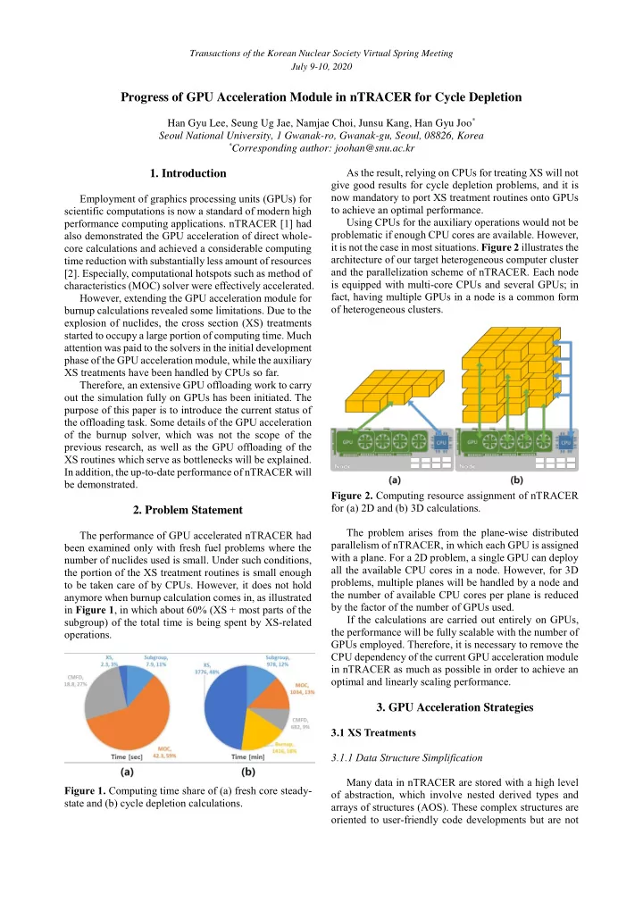
Figure 1. Computing time share of (a) fresh core steady- state and (b) cycle depletion calculations. As the result, relying on CPUs for treating XS will not give good results for cycle depletion problems, and it is now mandatory to port XS treatment routines onto GPUs to achieve an optimal performance. Using CPUs for the auxiliary operations would not be problematic if enough CPU cores are available. However, it is not the case in most situations. Figure 2 illustrates the architecture of our target heterogeneous computer cluster and the parallelization scheme of nTRACER. Each node is equipped with multi-core CPUs and several GPUs; in fact, having multiple GPUs in a node is a common form

  • f heterogeneous clusters.

Figure 2. Computing resource assignment of nTRACER for (a) 2D and (b) 3D calculations. The problem arises from the plane-wise distributed parallelism of nTRACER, in which each GPU is assigned with a plane. For a 2D problem, a single GPU can deploy all the available CPU cores in a node. However, for 3D problems, multiple planes will be handled by a node and the number of available CPU cores per plane is reduced by the factor of the number of GPUs used. If the calculations are carried out entirely on GPUs, the performance will be fully scalable with the number of GPUs employed. Therefore, it is necessary to remove the CPU dependency of the current GPU acceleration module in nTRACER as much as possible in order to achieve an

  • ptimal and linearly scaling performance.
  • 3. GPU Acceleration Strategies

3.1 XS Treatments 3.1.1 Data Structure Simplification Many data in nTRACER are stored with a high level

  • f abstraction, which involve nested derived types and

arrays of structures (AOS). These complex structures are

  • riented to user-friendly code developments but are not

Transactions of the Korean Nuclear Society Virtual Spring Meeting July 9-10, 2020

slide-2
SLIDE 2

friendly to the performance. Accessing data located deep inside a chain of derived types requires multiple pointer referencing and is completely segmented. Let alone the programmatic restrictions of handling such complicated data structures on GPUs, it can hardly satisfy the requirement of memory coalescing, which is

  • ne of the most important optimization requirements for

GPU kernels that adjacent threads should access memory

  • contiguously. Therefore, all the data should be cast into a

sequence of contiguous memory blocks, as illustrated in Figure 3. Figure 3. Data structure simplification process. Figure 3 shows an example of unfolding a dataset in which 2D arrays of different size are contained in each of the element of a derived type array. All the segmented 2D arrays are reshaped and gathered to form a monolithic 1D

  • array. To distinguish the segments on the large 1D array,

a displacement vector which contains the starting indices

  • f each segment is defined. An array that contains the size
  • f each segment is also accompanied. This is one of the

simplest cases, and more complicated mapping would be required for unrolling multi-dimensional datasets. 3.1.2 Macroscopic XS Calculation Calculation of macroscopic XS required in neutronics solvers is schematically straightforward but entails heavy arithmetic operations. For each region, reaction type, and group, the microscopic XS of the nuclides are interpolated by temperature and accumulated with number densities. The workload is directly proportional to the number of nuclides contained in each region.

, 1 1 2 1 , , , , 1 ,

, 1

iso iT k k iso k iso k iso iso iT iso iT

T T w w w T T

+ +

− = = − − (1)

( )

1 2 , , , , , , , , , , , 1 x k g k iso k iso x iso g iT k iso x iso g iT iso

N w w  

+

 = +

(2)

k : Index of a region iT : Index of a temperature point x : A type of reaction

1 , k iso

w : Interpolation weight at region k and nuclide iso

, iso iT

T

: Temperature at point iT of nuclide iso Note that the operations for each region and group are fully independent. Thus, each thread takes one region and

  • ne group, which yields millions of threads.

3.1.3 Effective XS Generation and Subgroup Fixed Source Problem (SGFSP) In the macro-level grid (MLG) scheme employed by nTRACER [3], the number of SGFSPs to be solved per each group is fixed to 8. The heterogeneity effects coming from the intra-pellet distributions of number densities and temperatures are handled by temperature consideration factors (TCF) and number density consideration factors (NDCF). The SGFSP formulations in the MLG scheme and definitions of the quantities are as follows:

( )

( )

( )

, , , , , , , , , , ,

1 = for fuel 4

fuel g m k T g m k k N g k pinavg m k p k g m k p k

f T f T      +  +  

(3)

( )

TargetReg , , , ,

1 = for clad and AIC 4

m k m k p k m k p k

     +  +  

(4)

( )

( ) ( )

, , , , , , , , ,

, ,

i i i i in k g k b g m k i reso T g m k k i i i i in k g pinavg b g m k i reso

N I T f T N I T  

= =

= 

(5)

( ) ( ) ( )

, , , , ,

,

i i i i in k g k b g m k i reso N g k pinavg k g pinavg k k k core k core

N I T f T RI T V V 

=  

=

  

(6)

, , , , , , , , , , , , ,

for fuel 1

g m k e g m k T g m k N g k m p k g m k

f f    =  −  − (7)

, , , , ,

for clad and AIC 1

m k e m k m p k m k

   =  −  − (8) Generation of effective XS of an isotope involves the calculation of the un-interfered cross section and then the resonance interference factor (RIF) of other isotopes by the RIF library method [4].

( )

( )

( )

* , , , , , , , , , , , , , , , , , , , , , , , , , , , , , r r r r x g n pinavg T g n k k x g n b g n k r r n a g n b g n k r alone eff x g k r r a g n pinavg b g n k r r n a g n b g n k

w T f T w T         + = +

 

(9)

 

, ,

1 1

i i j x g x g j RIFL

f f 

= + −

(10) Followed by an extensive restructuring of the legacy data, region- and group-wise parallelism were applied to all the operations exploiting the inherent independence. However, the calculation of NCDF in Eq. (6) requires core-wide reduction which is not fully parallelizable. For the NCDF calculation, therefore, region- and group-wise resonance integrals (RI) are first calculated in parallel and then the reduction operation is performed.

Transactions of the Korean Nuclear Society Virtual Spring Meeting July 9-10, 2020

slide-3
SLIDE 3

3.2 Burnup Calculation nTRACER has used Krylov subspace method for the matrix exponential solver [5], and recently it implemented Chebyshev rational approximation method (CRAM) [6]. Among the two solvers, the CRAM solver was chosen for the GPU acceleration. The rationale for the selection of the solver and optimization techniques will be described. 3.2.1 Iterative CRAM Solver For accuracy, CRAM usually employs direct method for the linear system solution. However, if the complexity

  • f the system is not high, iterative methods are sufficient

to obtain accurate solutions. It was proved that the target accuracy can be achieved with the iterative linear system solver in nTRACER burnup calculations. A beneficial feature of the iterative CRAM for GPUs is that the number of iterations required remains more-or- less the same regardless of the regions. This minimizes branch divergences in GPU kernels in which each thread takes a problem of a region. On the other hand, in Krylov solvers, the rank of Hessenberg matrices and the number

  • f scaling and squaring operations vary region to region,

which is not preferred for the GPU acceleration. In addition, the performance of the iterative CRAM is in fact superior to the Krylov solver. With proper iterative methods, only a few iterations are required thanks to the strong diagonal dominance of the systems, which makes the inverse calculations computationally cheap. For this work, BiCGSTAB with Jacobi preconditioner was applied to the iterative CRAM solver. 3.2.2 Optimization of the CRAM Solver Conceptually, saving matrix elements contiguously is the most natural way. However, the burnup problem is a batch of small linear system problems; each system only has 3,411 non-zeros but there are hundreds of thousands

  • f systems. As the region-wise (system-wise) parallelism

is applied, a special data layout was required for the GPU- based ‘batched’ iterative CRAM solver, which is shown in Figure 4. The key of the memory layout for the batched systems is that the sparsity patterns are identical. Even though the elements differ between the regions, the sparsity pattern is fixed as it is determined by the nuclide transition map given by a common burnup chain library. Utilizing this feature, the index vectors are stored in constant memory which is a special read-only cache memory accessible by all threads. In case of the matrix elements, they are saved in a non- zero-major ordering scheme; for each non-zero position, the corresponding elements of all the systems are stored

  • contiguously. As each thread is dealing with a system, the

threads will read the same non-zero location of different systems at each instruction cycle, whose accesses will be fully coalesced by the non-zero-major ordering. Figure 4. GPU memory structure in burnup calculations.

  • 4. Results and Discussion

The performance of the improved GPU-based solver is tested with an APR1400 [7] 2D quarter core problem. Table 1 shows the specification of the GPU workstation deployed. Table 1. Specification of the workstation. CPU 2 × Intel Xeon E5-2630 v4 20 Cores, 2.4 GHz (Boost) GPU NVIDIA GeForce RTX 2080 Ti (11 GB GDDR6) Compiler PGI Fortran 19.4 Intel Fortran 19.0.4 In the following, test cases are distinguished by ‘initial’ and ‘extended.’ The former resorts to CPUs for the XS tasks as it was in the initial version, and the latter extends the application range of GPUs to the XS calculations. In each case, the number of CPU cores used is varied to examine the impact of the CPU overhead to the overall

  • performance. Specifically, the number of CPU cores used

is changed from 5 to 20 and the performance impact was

  • examined. As mentioned in the problem statement, less

CPU cores are available per plane in 3D than in 2D in the current plane-per-GPU topology. As the result, one cannot expect a linear scale-up of performance from 2D to 3D. Therefore, the situation of extending from 2D to 3D was mimicked by using fewer CPU cores for the 2D problem instead of directly solving 3D problems. First of all, changes of MOC and subgroup computing time with respect to burnup were examined, as illustrated in Figure 5. The computing times are the averaged values in each burnup step, and two types of computing times are indicated; the time for the initial step in which the material compositions are fresh and the maximum measured time. As the number of nuclides skyrockets with depletion, the effectiveness of GPU-based XS treatments is clearly

  • revealed. It can be seen that the ‘initial’ cases suffer from

significant increase of computing time caused by the XS burden inflicted on CPUs. The performance degradation is especially critical with reduced number of CPU cores, which will likely be the case in 3D calculations. On the

  • ther hand, the ‘extended’ cases have almost no penalty

from burnup in performance and substantially outperform the ‘initial’ cases as the burnup proceeds.

Transactions of the Korean Nuclear Society Virtual Spring Meeting July 9-10, 2020

slide-4
SLIDE 4

Figure 5. Average computing time of (a) MOC and (b) subgroup kernels with respect to burnup. The calculation time of each procedure for all cases is shown at Figure 6. Note that for burnup calculation, the ‘CPU ONLY’ case employs a highly efficient Intel Math Kernel Library (MKL) based solver [8]. The burnup time being larger in the GPU-accelerated cases than the CPU- based one indicates the necessity of further tuning of the GPU-based burnup solver. Besides the MOC and SGFSP procedures, the time for XS routines has reduced tremendously. This reduction is more noticeable for limited CPU cores, remaining under 15% of the initial case. Also, the increment of time with fewer CPU cores was very small for extended cases. As a result, 8 hours of cycle depletion calculation time, which was the best result with only CPU cores, has been reduced to one and half hour by extensive GPU accelerations. In the meantime, the memory loaded on the GPU reached to 8.5 GB at most. Figure 6. Time share of depletion calculations.

  • 5. Conclusion

More extensive application of GPUs in nTRACER for the XS calculations and the burnup calculations has been

  • made. Previous work had focused on developing the GPU

acceleration algorithms for the main solvers such as MOC, CMFD, and axial sweep. Auxiliary routines including XS treatments had relied on CPUs primarily for relieving the programming burden by utilizing existing routines and secondarily for exploiting spare CPU resources. However, this revealed limitations in cycle depletion calculations in which the computational cost of the auxiliary routines is not negligible anymore, which necessitated this work. For a complete GPU offloading of the XS treatment routines, all the data in nTRACER have been cast into a more compute-friendly memory layout, followed by the implementation of corresponding calculation kernels. For the GPU acceleration of burnup calculations, an iterative CRAM solver applying BiCGSTAB was introduced for efficiency, and a special linear system storage scheme that takes advantage from the common sparsity of the batched systems was devised, which optimizes the memory access patterns under the system-wise parallelism. As the result, most of the procedures in nTRACER for cycle depletion had been offloaded to GPUs and the CPU bottlenecks had been largely resolved. This guarantees a fully scalable performance from 2D to 3D regardless of the number of CPU cores. Acknowledgements

This research is supported by National Research Foundation of Korea (NRF) Grant No. 2016M3C4A7952631 (Realization of Massive Parallel High Fidelity Virtual Reactor)

References

[1] Y. S. Jung, C. B. Shim, C. H. Lim and H. G. Joo, “Practical Numerical Reactor Employing Direct Whole Core Neutron Transport and Subchannel thermal/hydraulic Solvers,” Annals

  • f Nuclear Energy 62, pp. 357-374, 2013.

[2] N. Choi, J. Kang, H. G. Joo, “Preliminary Performance Assessment of GPU Acceleration Module in nTRACER,” Transactions of the Korean Nuclear Society Autumn Meeting, Yeosu, Korea, Oct. 24-25, 2018. [3] H. Park and H. G. Joo, “Effective subgroup method employing macro level grid optimization for LWR applications,” Annals of Nuclear Energy, 129, pp. 461-471, 2019. [4] S. Choi, A. Khassenov, D. Lee, “Resonance Self-Shielding Method with Resonance Interference Factor Library,” Journal of Nuclear Science and Technology 53(8), pp. 1142-1154, 2016. [5] A. Yamamoto, M. Tatsumi, N. Sugimura, “Numerical Solution of Stiff Burnup Equation with Short Half Lived Nuclides by the Krylov Subspace Method,” Journal of Nuclear Science and Technology 44(2), pp. 147-154, 2007. [6] M. Pusa, “Rational Approximations to the Matrix Exponential in Burnup Calculations,” Nuclear Science and Engineering 169(2), pp. 155-167, 2011. [7] H. Hong and H. G. Joo, “Analysis of the APR1400 PWR Initial Core with the nTRACER Direct Whole Core Calculation Code and the McCARD Monte Carlo Code,” Transactions of the Korean Nuclear Society Spring Meeting, Jeju, Korea, May 18- 19, 2017. [8] N. Choi et al., “Recent Capability and Performance Enhancements of the Whole-Core Transport Code nTRACER,” Proceedings of the International Conference on Physics of Reactors, Cambridge, United Kingdom, Mar. 29 – Apr. 2 (2020). Transactions of the Korean Nuclear Society Virtual Spring Meeting July 9-10, 2020