
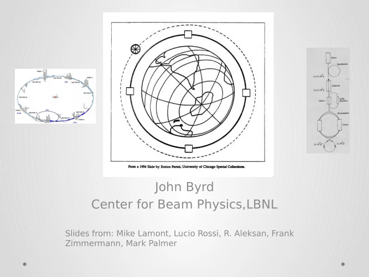
SLIDE 1
John Byrd Center for Beam Physics,LBNL
Slides from: Mike Lamont, Lucio Rossi, R. Aleksan, Frank Zimmermann, Mark Palmer
John Byrd Center for Beam Physics,LBNL Slides from: Mike Lamont, - - PowerPoint PPT Presentation
John Byrd Center for Beam Physics,LBNL Slides from: Mike Lamont, Lucio Rossi, R. Aleksan, Frank Zimmermann, Mark Palmer This talk reviews the ring options. VLEP LHC Status: Integrated luminosity 2010-2012 201 Commissioning 0 201
John Byrd Center for Beam Physics,LBNL
Slides from: Mike Lamont, Lucio Rossi, R. Aleksan, Frank Zimmermann, Mark Palmer
VLEP This talk reviews the “ring” options.
LHC Status: Integrated luminosity 2010-2012
201 Commissioning 201 1 Exploring the limits 201 2 Production+ 3.5 T eV 5.6 fb-1 4 T eV ~21 fb-1 Never stop exploring
– Move to nominal bunch intensity, and beyond with double batch 50 ns – and the LHC can take it
– 67% of nominal
– Use of available aperture and tight collimator settings – opened the way to the squeeze to 60 cm
All this not without its
squeeze and going into collisions with high-bunch intensities
extremely promising future.
Performance & T echnical (Consolidation)
Shut down to fix interconnects and overcome energy limitation (LHC incident
and R2E
Shut down to
beam intensity limitation (Injectors, collimation and more…)
Full upgrad e
HiLumi: T wo branches (with
upgrade (1000-1200 fb-1)
enhanced cooling
separation Arc form RF and from IR
(3000 fb-1)
aperture
3000 fb-1
LBNL involvement
3 fb-1 per day 60% of efficiency 250 fb-1 /year 300 fb-1/year as «ultimate»
Full project Enhanced consolidatio
work supported by the European Commission under the FP7 Research Infrastructures project EuCARD, grant agreement no. 227579
Frank Zimmermann HF2012, FNAL, 15 November 2012
Thanks to R. Assmann, P . Azzi, M. Bai, A. Blondel, H. Burkhardt, A. Butterworth, Y . Cai, A. Chao, W. Chou, P . Collier, J. Ellis, M. Fitterer, P . Janot, M. Jimenez, M. Klute, M. Koratzinos, A. Milanese, M. Modena, S. Myers,
Silari, D. Summers, V. Telnov, R. Tomas, J. Wenninger, U. Wienands,
PSB PS (0.6 km) SPS (6.9 km)
LHC (26.7 km)
TLEP (80 km, e+e-, up to ~350 GeV c.m VHE-LHC (pp, up to 100 TeV c.m.)
LEP3 (e+e-, 240 GeV c.m.)
circular Higgs factories at CERN & beyond
+ inexpensive (<0.1xLC) + tunnel exists + reusing ATLAS and CMS detectors + reusing LHC cryoplants
+ higher energy reach, 5-10x higher luminosity + decoupled from LHC/HL-LHC operation & construction + tunnel can later serve for HE-LHC (factor 3 in energy from tunnel alone) with LHC remaining as injector
Fermilab
key parameters
(e+e- -> ZH, e+e- → W+W-, e+e- → Z,[e+e-→ t ) LEP3 TLEP circumference 26.7 km 80 km max beam energy 120 GeV 175 GeV max no. of IPs 4 4 luminosity at 350 GeV c.m.
cm-2s-1 luminosity at 240 GeV c.m. 1034 cm-2s- 1 5x1034 cm- 2s-1 luminosity at 160 GeV c.m. 5x1034 cm- 2s-1 2.5x1035 cm-2s-1
at the Z pole repeating LEP physics programme in a few minutes…
Either using existing LEP/LHC tunnel to reach 26-32 TeV collisions Or build (or reuse) a 80km tunnel to reach 80-100 TeV collisions
both cases, SC challenge to develop 16-20 Tesla magn
workshops
Proton source: For example PROJECT X at 4 MW, with 2±1 ns long bunches Goal: Produce a high intensity µ beam whose 6D phase space is reduced by a factor of >106 from its value at the production target Collider: √s = 3 T eV Circumference = 4.5km L = 3×1034 cm-2s-1 µ/bunch = 2x10¹² σ(p)/p = 0.1% ε⊥N = 25 µm, ε//N=72 mm β* = 5mm
Muon Collider Block Diagram
LBNL involvement
Muon Collider - Neutrino Factory Comparison
NEUTRINO FACTORY MUON COLLIDER Share same complex ν Factory Goal: O(1021) µ/year within the accelerator acceptance
year Feasibility Assessment in 2 phases:
needed for a Muon Collider
the International Design Study for a Neutrino Factory
facility that can support unsurpassed Intensity and Energy Frontier research
a Enable an informed decision
HEP community
Muon Collider Concept
A challenging, but promising, R&D program lies ahead!
T echnical Challenges: T arget & Front End
ertiary production
arget Demonstration: MERIT Experiment with Hg Jet Capable of 8MW of beam power @ 70 Hz repetition rate
µ/year within the acceptance of an accelerator
Neuffer
T echnical Challenges: Cooling
gradient to compensate for the energy loss in absorbers
magnetic fields
Spectrometer Solenoids RF-Coupling Coil (RFCC) Units
The Muon Ionization Cooling Experiment: Demonstrate the method and validate
MTA Beamline
Emittance Goal Longitudinal space charge bound
Transverse Emittance (
µ
m) Longitudinal Emittance (mm) 101 102 103 104 100 101 102 1 2 3 4 5 6 6a 7a 7
Some components beyond state-of-art:
(30-40 T)
esla fields
the 6D phase space by a factor of O(106) → MC luminosity of O(1034) cm-2s-1-2 s-1
Emittance Reduction via Ionization Cooling
The program targets critical magnet and cooling cell technical demonstrations within its feasibility phase.
Initial Emittance
T echnical Challenges: Acceleration and Collider
a Beyond the capability of most machines
Superconducting Linacs Recirculating Linear Accelerators (RLAs) Fixed-Field Alternating-Gradient (FFAG) machines Rapid Cycling Synchrotrons (RCS) Hybrids
EMMA
– Emittances are relatively large, but muons circulate for ~1000 turns – High field dipoles and quadrupoles
– Challenging detector backgrounds and shielding issues
MARS magnet energy deposition (1.5 T eV) M A R S d e t e c t o r b a c k g r o u n d
Feasibility Assessment: Phase I Phase I Review Feasibility Assessment: Phase II Technical Feasibility Report Design & Simulation Technology Demonstrations System Demonstrations: MICE 6D Cooling Demonstration
Q2 Q3 Q4 Q1 Q2 Q1FY13 FY14 FY15 FY16 FY17 FY18
Q3 Q4 Q1 Q2 Q3 Q4 Q1 Q2 Q3 Q4 Q1 Q2 Q3 Q4 Q1 Q2 Q3 Q4Ph a se I Est im a t e d 6
a r Tim e sca le t
m p le t e Pro g ra m w it h Pro p
d Bu d g e t Pro file In it ia l Ba se lin e s & Pe rf Ev a l H ig h Le v e ra g e Alt e rn a t iv e s Ph a se II Te ch n
g y D e m
st ra t io n s Ev a lu a t e & Re fin e Ba se lin e Co n ce p t s Pu rsu e H ig h Le v e ra g e Alt e rn a t iv e s Ph a se II Ph a se I Te ch n
g y D e m
st ra t io n s D
m e n t D e sig n s H PC To
p le m e n t M issin g Ph y sics M ICE St e p IV M ICE St e p VI Ta rg e t M ICE RFCC Fa b rica t io n Ba se lin e
Sp e ct So l.'s
M TA: Va cu u m RF R& D , H PRF R& D , M ICE RF Te st s, Co
g Ce ll Te ch n
g y Te st s... Fe a sib ilit y Pro p
l Crit ica l En g in e e rin g Co n ce p t s/D e sig n s 6 D Co
g D e m
st ra t io n Pla n n in g
VLEP 14 TeV CoM 3 ab-1 by 2035 VLEP 250 GeV CoM Feasible for 80+km ring VLHC 80-100 TeV CoM Feasible for 80+km ring with 16-20 T dipoles MHF 126 GeV CoM >1 TeV CoM energy frontier Feasibility report in 2018