J T b J. Toby Mottram, DSc, FIStructE M tt DS FISt tE School of - - PDF document

j t b j toby mottram dsc fistructe m tt ds fist te school
SMART_READER_LITE
LIVE PREVIEW

J T b J. Toby Mottram, DSc, FIStructE M tt DS FISt tE School of - - PDF document

Design Guidance for Bolted Connections in Design Guidance for Bolted Connections in Structures of Pultruded Shapes: Gaps in Knowledge Structures of Pultruded Shapes: Gaps in Knowledge J T b J. Toby Mottram, DSc, FIStructE M tt DS FISt tE


slide-1
SLIDE 1

1

J T b M tt DS FISt tE Design Guidance for Bolted Connections in Design Guidance for Bolted Connections in Structures of Pultruded Shapes: Gaps in Knowledge Structures of Pultruded Shapes: Gaps in Knowledge

  • J. Toby Mottram, DSc, FIStructE

School of Engineering

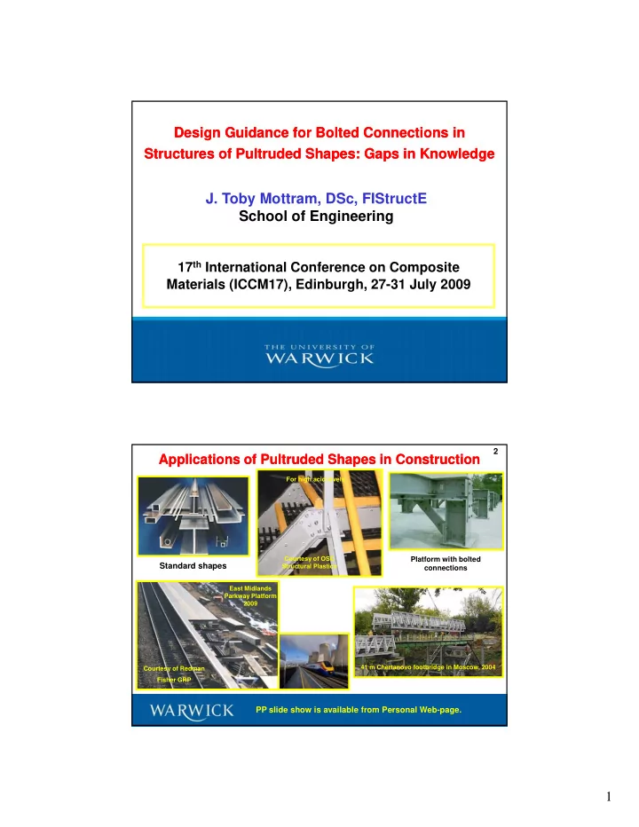
17th International Conference on Composite Materials (ICCM17), Edinburgh, 27-31 July 2009 Materials (ICCM17), Edinburgh, 27 31 July 2009 Applications of Pultruded Shapes in Construction Applications of Pultruded Shapes in Construction

2

For high acid levels East Midlands Parkway Platform 2009 Courtesy of OSC Structural Plastics

Platform with bolted connections

Standard shapes PP slide show is available from Personal Web-page.

Courtesy of Redman Fisher GRP 41 m Chertanovo footbridge in Moscow, 2004

slide-2
SLIDE 2

2 How were Gaps in Knowledge found How were Gaps in Knowledge found

“Standard for Load and Resistance Factor Design (LRFD) of Pultruded Fiber-Reinforced Polymer (FRP) Structures” (American Society of Civil Engineers and American Composite Manufacturers Association (Pultrusion Industry Council)).

3

Eight chapters, we contribute for the “glory of it”.

  • 1. GENERAL PROVISIONS
  • 2. DESIGN RESISTANCE
  • 3. TENSION MEMBERS
  • 4. DESIGN OF COMPRESSION MEMBERS

5. DESIGN FOR MEMBERS IN BENDING AND SHEAR 6. MEMBERS UNDER COMBINED FORCES AND TENSION

  • 7. PLATES AND BUILT-UP MEMBERS
  • 8. BOLTED CONNECTIONS.

Expected ASCE publication in 2011 LRFD chapter for bolted connections combines design for frame joints, such as the web-cleated type shown on top- right (classify as simple using the

Connections and Joints Permitted Connections and Joints Permitted

4 Cleat

g ( y p g principles in BS EN 1993-1-8:2006), with the design

  • f

plate-to-plate connections, such as there is in each of the cleat legs and bracing members (bottom-right). Drafting combined information from

Bracing member

g researchers and pultruders with design rule provisions found in design standards for other structural materials.

member

slide-3
SLIDE 3

3 Reasons for the Gaps in Knowledge Reasons for the Gaps in Knowledge

5

Why Research Papers can rarely be used for the basis of design rules:

  • No clear definition of the domain of applicability of the conclusions.
  • No critical review of previous research relevant to that domain.
  • Conclusions that are recommendations for more research.
  • A design method that needs data which will not be available to the designer,
  • r which itself depends on other variables.
  • Test results that omit crucial data.
  • Test results that exceed proposed design resistance mainly because strength
  • f the materials far exceed the proposed design (i.e., factored) values.
  • Theory based on unvalidated assumptions, or that fails to take account of

imperfections likely to occur in practice.

So Why are there Gaps in Knowledge So Why are there Gaps in Knowledge

6

  • Conclusions applicable only within a particular environment of specifications

and practice.

  • An investigation based on literature in one language only, leading to a theory

that is not checked against test data reported in another language It is not that is not checked against test data reported in another language. It is not sufficient that the theory predicts the author’s test results! Nine reasons can be identified when evaluating what is known from the ‘200’ publications to the bolted connections’ chapter.

slide-4
SLIDE 4

4 Gaps in Knowledge Gaps in Knowledge

7

Paper lists 20 questions that need to be addressed, examples are:

What are to be the recommended details for: connection geometries (e.g. hole clearance, end distance, side distance, pitch, etc.); bolt, nut and washer types; bolt installation torque? Is it acceptable to have a joint with a single bolt? What is to be the standard test method that shall be specified to determine pin-bearing strength? How does pin-bearing strength vary with environmental conditioning, bolt shaft flexure, position of bolt in clearance hole, orientation of ‘bearing’ force to the

  • rientation of the FRP material?

What is the strength reduction factor when loading is for the single-lap plate-to-plate configuration and the basic resistance formulae are based

  • n a double-lap test

arrangement?

Gaps in Knowledge Gaps in Knowledge

8 How do we predict strength when there are two or more rows of bolting (i.e. when the by-pass loading exists and there is a requirement to know the open-hole stress concentration factor)? What is the distribution of the connection force between the bolts in multi-rows? How is the strength of connections affected by a combination of in- and out-of-plane actions (as found in frame joints)? What is the strength of connections for bracing members with eccentric loading? What is the moment-rotation response of ‘prescriptive’ web-cleated (‘pinned’) connections that fail by the prying action causing the FRP cleats or columns to delaminate? Can the rotational and in-plane stiffnesses be characterized such that analysis can be used to check if frame deformation satisfies a serviceability limit state?

slide-5
SLIDE 5

5 ASCE Standard ASCE Standard-

  • Bearing Strength Formula

Bearing Strength Formula

t is thickness of FRP. d is diameter of bolt.

br br 

F

d t R 

b

9

is the specified pin-bearing strength for the orientation

  • f the resultant force at the bolt/FRP contact with respect

to the direction of pultrusion. Is there an expression for , given that we use a standard test method to determine and ? From ASCE-16-95 the expression (Hankinson-type) for interpolating between parallel (0o) and perpendicular (90o) to wood grain loading is

br 

F

br 

F

br 90

F

br

F

parallel (0o) and perpendicular (90o) to wood grain loading is . Is this expression what we require?

 

 2 2

cos sin

br 90 br br 90 br br

F F F F F  

0.85 0.90 0.95 1.00

Ascione et al. 2009 Wood expression

10

ASCE Standard ASCE Standard-

  • Bearing Strength Formula

Bearing Strength Formula

No

0.60 0.65 0.70 0.75 0.80

br 90 br

F F

 

 2 2

cos sin

br 90 br br 90 br br

F F F F F  

No

0.50 0.55 15 30 45 60 75 90 Orientation FRP material degrees

This is a gap in our knowledge

slide-6
SLIDE 6

6

ASCE Standard ASCE Standard – – Net Net-

  • tension

tension

Resistance of a double lap shear connection with multi-rows of bolts

s e1 s pitch distance end distance

11

e2 g dn

Direction

  • f

pultrusion t Tensile load Tensile load side distance gage distance plate thickness

Testing often has outer plates of steel (ASTM and EN standards)

Tensile load Tensile load Bolts of diameter d (< dn) are not shown First bolt row for inner plate of thickness t

ASCE Standard ASCE Standard – – Net tension Net tension

Net-tension failure for connections with two rows of bolts

Tension load

12 12

Ultimate Load Damage Failure Load d

First bolt row Tension load

 = 0

Stroke Tensile load

For this failure mode the damage and ultimate loads can be the same.

Sources: PhD theses, C. Lutz (2005) & P. Wang (2004)

load

slide-7
SLIDE 7

7 ASCE Standard ASCE Standard – – Net Net-

  • tension

tension

Net-tension failure for connections with two rows of bolts Locations for stress concentrations causing failure

Peak stresses are at points A 13 13 Stroke Tensile load ‘Linear elastic’ response to rupture

Tension load

Stroke

Source: PhD thesis, P. Wang (2004)

Assumed net-tension failure plane for resistance model

e1 w = 2e2

ASCE Standard ASCE Standard – – Net Net-

  • tension

tension

Model for net-tension resistance, this is Rnt,f

14 14

Filled-hole Open-hole

LbrRnt,f/2 (1-Lbr) Rnt,f/2 n t e1 dn d A Tension stress due to LbrRnt,f Peak stress at hole due to bearing load stress at free edge Hole d (1-Lbr) Rnt,f/2 LbrRnt,f/2 A A Tension stress due to (1-Lbr)Rnt,f stress at free edge Hole Peak stress at hole due to bypass load s = 4d min. Row 2 Row 1 Rnt,f t centre Rnt,f centre

Net-tension failure plane

slide-8
SLIDE 8

8 ASCE Standard ASCE Standard – – Net Net-

  • tension

tension

Semi-empirical model by Hart-Smith (1987) Developed for aircraft and aerospace structures of laminated FRPs

        w is width t is thickness 15 15

 

t L br L

  • p,

br L nt, nt,f

1 1 1 F t w w d L K d w L K R

n

                                                          d is bolt diameter dn is hole diameter Lbr proportion of tension load taken in bearing by first bolt row (steel and FRP Lbr = 0.6 (A gap!)) i L it di l t il t th f th lt d d t i l (L 0 d )

t

F is Longitudinal tensile strength of the pultruded material. (L  0 degrees) Knt,L depends on geometry and a filled-hole correlation coefficient (CL). Kop,L depends on geometry and an open-hole correlation coefficient (Cop,L).

t L

F

Model for case when loading direction and orientation of pultruded material are aligned ( = 0).

0.8

ASCE Standard ASCE Standard – – Net Net-

  • tension

tension

Evaluation of semi-empirical model by Hart-Smith (1987)

Not time to discuss all issues for evaluation!! Open hole correlation coefficient, Cop,L

3

  d 16 16 is the isotropic stress concentration factor. ktc is the orthotropic stress concentration determined by experiment using open

0.4 0.6 0.8

ktc - 1

1 1

  • p

te, tc L

  • p,

   k k C

3 n

  • p

te,

1 2          w d k

= 0.374 (mean), CoV 23.5%

hole specimens with different dn/w ratios.

0.2 1.0 1.2 1.4 1.6

kte,op -1 Test results from G. J. Turvey and P. Wang, 'Open-hole strength of pultruded plate,' Structures & Buildings, 156 1, 2003, 93-101.

Not linear relationship! Different material – another gap

slide-9
SLIDE 9

9

1.40

ASCE Standard ASCE Standard – – Net Net-

  • tension

tension

Net-tension failure for connections with two rows of bolts. Plotted Longitudinal connection results required three studies.

Each test number is for a different connection h i RT with as-received material 17 17

0.40 0.60 0.80 1.00 1.20 R nf,f,exp/R nf,f,theory

geometry, having constant bolt diameter and type, plate thickness and tightening torque. Only 8 test results, without duplication – yet another gap. Need more l h

CL = 0.33 (bearing); Cop,L = 0.37 (by-pass); t = 12.7 mm; d = 19.05 mm; dn = 20.6 mm; = 166 N/mm2 (mean); torque is 32 5 N m

t L

F

0.00 0.20 2 4 6 8 10 12 Test Number

test results that correspond to what the design standard is to permit.

166 N/mm (mean); torque is 32.5 N.m

L

F

J . T. Mottram, ‘Prediction of net–tension strength for multi-row bolted connections of pultruded material using the Hart-Smith semi-empirical modeling approach,’ Composites for Construction.

  • If research is to be ‘useful’ for the basic of design rules it is essential for the work

to be planned to correspond to what the standard is to permit.

  • Because there are ‘no’ rules for the design of pultruded FRP frames with bolted

Concluding Remarks Concluding Remarks

19

connections it is unsurprising that many research papers fail to report all information necessary for code writing.

  • By drafting a chapter for the design of bolted connections we have identified 20

questions that specify our gaps in knowledge (others may follow).

  • These questions provide a framework for further targeted research whose

deliverables will enable code writers to refine and improve proposed design provisions (based on what is known and understood today).

slide-10
SLIDE 10

10

Thank you for your attention. Any questions?

Email: Toby.Mottram@warwick.ac.uk 2009