
SLIDE 1
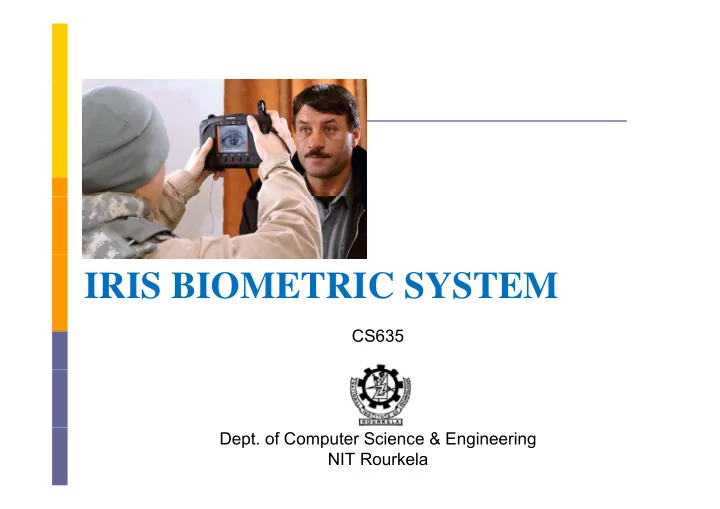
IRIS BIOMETRIC SYSTEM
CS635
- Dept. of Computer Science & Engineering
NIT Rourkela
IRIS BIOMETRIC SYSTEM CS635 Dept. of Computer Science & - - PowerPoint PPT Presentation
IRIS BIOMETRIC SYSTEM CS635 Dept. of Computer Science & Engineering NIT Rourkela Iris Biometrics Iris is externally-visible, colored ring around the pupil The flowery pattern is unique for each individual The right and left eye
CS635
NIT Rourkela
Eyelash Iris Boundary Pupil Boundary Pupil Iris Iris Sclera E lid Eyelid
Hi hl d i l f h Highly protected, internal organ of the eye Externally visible patterns imaged from a distance Externally visible patterns imaged from a distance Patterns apparently stable throughout life Iris shape is far more predictable than that of the face No need for a person to touch any equipment
L li i f il f d k i i Localization fails for dark iris Highly susceptible for changes in weather or due to infection Highly susceptible for changes in weather or due to infection Obscured by eyelashes, lenses, reflections Well trained and co-operative user is required Expensive Acquisition Devices
Occlusion due to eyelashes
The remarkable story of Sharbat Gula, first photographed in 1984 aged 12 in a refugee camp in Pakistan by National Geographic photographer Steve
6
g y g g McCurry, and traced 18 years later to a remote part of Afghanistan where she was again photographed by McCurry, is told by National Geographic in their magazine (April 2002 issue)
Geographic turned to the inventor of automatic iris recognition, John Daugman, a professor of computer science at England’s University of Cambridge His biometric technique uses computer science at England s University of Cambridge. His biometric technique uses mathematical calculations, and the numbers Daugman got left no question in his mind that the haunted eyes of the young Afghan refugee and the eyes of the adult Sharbat Gula belong to the same person.
7
Fl d S fi Flom and Safir Daugman’s Approach Daugman s Approach Wildes Approach Proposed Implementation
I 1987 h h b i d f i l d In 1987 the authors obtained a patent for an unimplemented conceptual design of an iris biometrics system Their description suggested
highly controlled conditions headrest target image to direct the subject’s gaze manual operator p Pupil expansion and contraction was controlled by changing the illumination to force the pupil to a predetermined size
T d h il To detect the pupil,
Threshold based approach
Extraction of Iris Descriptors
Pattern recognition tools Ed d t ti l ith Edge detection algorithms Hough transform
Iris features could be stored on a credit card or identification card to support a verification task
I t Fl d fi ’ h Improvements over Flom and safir’s approach
Image should use near-infrared illumination
An integro-differential operator for detecting the iris boundary by searching the parameter space.
mapping the extracted iris region into polar coordinate system
F E di Feature Encoding
2D Wavelet demodulation
Matching
Hamming distance, which measures the fraction of bits for which two iris codes disagree codes disagree
Wildes describes an iris biometrics system developed at Sarnoff Wildes describes an iris biometrics system developed at Sarnoff Labs Image Acquisition Image Acquisition
a diffuse light source low light level camera
Iris Localization
Computing an binary edge map Hough transform to detect circles Hough transform to detect circles
Feature Extraction
Laplacian of Gaussian filter at multiple scales Laplacian of Gaussian filter at multiple scales
Matching
normalized correlation normalized correlation
Image Acquisition Preprocessing Preprocessing Iris Localization
Pupil Detection Iris Detection
Iris Normalization Feature Extraction Feature Extraction
Haar Wavelet
Matching
Th i i i i i d f The iris image is acquired from a CCD based iris camera Camera is placed 9 cm a a from Camera is placed 9 cm away from subjects eye The source of light is placed at a The source of light is placed at a distance of 12 cm (approx) from the user eye The distance between source of light and CCD camera is found to be approximately 8 cm pp y
Image Acquisition System: (a) System with frame grabber (b) CCD Camera (c) Light Source (d) User
Bi i i Binarization Find the complement of binary image Find the complement of binary image Hole filling using four connected approach Complement of hole filled image
Preprocessing and noise removal
Pupil Detection Iris Detection
Thresholding Edge Detection Circular Hough Transform
P il i h d k i f h Pupil is the darkest portion of the eye The pupil area is obtained after thresholding the input image The pupil area is obtained after thresholding the input image
Af h h ldi h i d i b i d i C d After thresholding the image edge is obtained using Canny edge Detector
CHT i d f f d i i h i CHT is used to transform a set of edge points in the image space into a set of accumulated votes in a parameter space For each edge point, votes are accumulated in an accumulator array for all parameter combinations. The array elements that contain the highest number of votes indicate the presence of the shape p p
F d i l ( ) fi d h did i i For every edge pixel (p) find the candidate center point using
p t
p t p
where xp and yp is the location of edge point p r є [rmin rmax] xt and yt is the determined circle center
F f di For range of radius
The center point is computed The Accumulator array is incremented by one for calculated center point y y p Accum[xt,yt,r]=Accum[xt,yt,r]+1
The point with maximum value in the accumulator is denoted as circle center with radius r
Histogram Equalization Concentric Circles of different radii are drawn from the detected pupil center The intensities lying over the perimeter of the circle are summed up up Among the candidate iris circles, the one having a maximum g , g change in intensity with respect to the previous drawn circle is the iris outer boundary
(a) Histogram Equalization (b) Concentric Circles (c) Iris Detected
L li i i i f i d li h l i f h Localizing iris from an image delineates the annular portion from the rest of the image The annular ring is transformed to rectangular ring The coordinate system is changed by unwrapping the iris from Cartesian coordinate their polar equivalent
p p
i i i p p
i i i
where rp and ri are respectively the radius of pupil and the iris while (xp(θ), yp(θ)) and (xi(θ), yi(θ)) are the coordinates of the ill d li bi b d i i th di ti θ Th l f θ pupillary and limbic boundaries in the direction θ. The value of θ belongs to [0;2], ρ belongs to [0;1]
O di i l t f ti h f ll d b One dimensional transformation on each row followed by one dimensional transformation of each column. Extracted coefficients would be
Approximation Vertical Vertical Horizontal Diagonal
Approximation coefficients are further decomposed into the next level level 4 level decomposition is used
Graphical Representation - Wavelet decomposition (le el 2) (level = 2)
2 2 9 5 2 5 2 4 14 4 2 7 2 3
Column wise Summation
6 7 4 7 3 4 8 8 13 11
7 16
Row wise Summation
6 21 2 7 3 10 5 1 3 5
Approximation Horizontal
6 21 2 7 20 27
2 7
1
Finding Average
3 10.5 1 3.5 10 13.5
1 3.5
0.5 6
3
Vertical Diagonal
Iris Strip after Decomposition
A l l 4 ffi i i bi d i i l f At level 4 coefficient matrices are combined into single feature matrix or feature template FV= [CD4 CV4 CH4].
where Iris is the binarized iris code
D b l (S) i h d i h h l (T) i Database template (S) is matched with the query template (T) using Hamming distance approach
n
m n j i j i j i Iris
S T m n MS
1 1 , ,
1
where n X m is the size of template and is the bitwise xor
Bath University MMU UBIRIS Casia V3 IIT Kanpur
Name Images (Subject × Images per subject = Total Images) BATH 50 × 20 = 1000 CASIA V3 249 × 11 ≈ 2655 (approx) Iris IITK 600 × 3 = 1800
Database Accuracy (%) FAR (%) FRR (%) IIT Kanpur 94.87 1.06 9.18
R %
IIT Kanpur 94.87 1.06 9.18 Bath University 95.08 2.33 7.50 CASIAV3 95.07 4.71 5.12
FAR FRR %
90 100 IITK BATH CASIAV3 80 90 CASIAV3 70 Accuracy 50 60 0.1 0.2 0.3 0.4 0.5 0.6 40 Threshold
Accuracy Graph vs. Threshold Graph
Haar Wavelet
LOG Gabor Wavelet
Weighted Sum of Score technique where α and β are static value of weights
Gabor Haar final
MS MS MS
where α and β are static value of weights
Table Showing accuracy values in percentage for BATH and
Databases → BATH IITK
g y g CASIA database
Approaches ↓ FAR FRR Acc FAR FRR Acc Haar Wavelet 1.61 11.08 93.64 0.33 7.88 95.89 LOG Gabor 1.63 9.55 94.40 1.30 6.05 96.31 Fusion 0.36 8.38 95.62 0.16 4.50 97.66
(a) BATH (b) IITK
(a) BATH (b) IITK
Harris Corner Detector
Autocorrelation matrix
(x y) (x, y)
coordinates of ith corner point
Hi
entropy information of window (wi ) around the corner entropy information of window (wi ) around the corner
Stage 1: Pairing corner points using Euclidean distance Stage 2: Finding Mutual Information (MI) of potential corners
ROC Curve for Euclidean, MI and Dual Stage approach on CASIA Dataset g
Table: Bin miss rate for different clusters using FCM and K-means
FCM K-means 2 1 3 2 4 3 1 5 8 8 6 11 12 7 12 18 8 16 21 8 16 21 9 17 25
20 25 FCM K Means 15 s Rate 10 Bin Miss 5 2 3 4 5 6 7 8 9 Number of Clusters
Graph showing bin miss rate by varying number of clusters for FCM and K-Means
F d i bl k i DCT Features are extracted using blockwise DCT Coefficients are reordered into subbands Coefficients are reordered into subbands Histogram is obtained for each subband (Hi) A global key is obtained using histogram binning approach B-tree is traversed using global key
S bb d (#) CASIA BATH IITK Subband (#) CASIA BATH IITK Classes (#) BM PR Classes BM PR Classes BM PR 1 2 0.00 99.69 5 04 26.14 5 1.5 41.44 2 5 1.60 35.96 23 12 7.69 19 5.0 17.21 3 16 3.60 22.70 66 26 3.04 46 5.5 9.24 4 39 13.2 10.23 130 36 1.42 93 10.0 4.77 5 82 24.0 6.12 197 38 0.92 148 12.5 3.25 6 158 30 8 3 46 313 56 0 49 252 15 5 1 56 6 158 30.8 3.46 313 56 0.49 252 15.5 1.56 7 233 35.6 2.63 399 60 0.30 396 20.5 0.92 8 304 40.0 1.77 492 70 0.16 584 29.0 0.50 9 387 42.0 1.22 583 72 0.09 744 37.5 0.27 10 519 43.6 0.63 648 72 0.06 856 44.0 0.20
Uses Hessian Matrix Uses Hessian Matrix Descriptor is formed using Haar Wavelet responses
BATH CASIA IITK Approaches FAR FRR Acc FAR FRR Acc FAR FRR Acc Gabor 1.63 8.02 95.16 3.47 44.94 75.78 2.64 21.09 88.13 Harris 29.04 39.03 65.97 17.18 34.73 74.05 24.95 21.95 76.55 SIFT 0 77 16 41 91 54 15 12 28 22 78 32 1 99 31 37 83 31 SIFT 0.77 16.41 91.54 15.12 28.22 78.32 1.99 31.37 83.31 SURF 2.66 6.36 95.48 4.58 3.85 95.77 0.02 0.01 99.98
Database → BATH CASIA IITK Test cases ↓ FAR FRR Acc FAR FRR Acc FAR FRR Acc Test cases ↓ FAR FRR Acc FAR FRR Acc FAR FRR Acc Normalized Iris 10.35 21.11 84.26 3.31 5.13 95.77 0.86 5.52 98.60 Annular Iris 2.37 1.97 97.84 1.44 4.07 97.23 4.65 1.41 97.15
IBM L k Ai li S i i h E IBM Looks Airline Security in the Eye IrisGuard, Inc. Securimetrics Inc Securimetrics, Inc. Panasonic London Heathrow Airport Amsterdam Schiphol Airport Charlotte Airport USA I i A LG C S th K IrisAccess LG Corp, South Korea IrisPass OKI Electric Industries, Japan EyeTicket Corp USA EyeTicket Corp. USA
Source: http://www cl cam ac uk/~jgd1000/afghan html Source: http://www.cl.cam.ac.uk/~jgd1000/afghan.html
Employees at Albany International Airport (NY)
Frequent Flyers at Schiphol Airport (NL)
Frequent Flyers at Schiphol Airport (NL) may enroll in the "Privium" programme, enabling them to enter The Netherlands without passport presentation enabling them to enter The Netherlands without passport presentation.
Condominium residents in Tokyo gain entry to the building by their iris patterns, and the elevator is automatically called and programmed to bring them to their residential floor. y p g g
United Nations High Commission for Refugees administers cash grants to refugees returning into Afghanistan
Frequent Flyers at Frankfurt/Main Airport can pass quickly through Immigration Control without passport inspection if their iris patterns have been enrolled for this purpose without passport inspection if their iris patterns have been enrolled for this purpose.
The check-in procedure for passengers at Narita Airport (Japan) is expedited by recognition of their iris patterns recognition of their iris patterns
A K J i A R d S P bh k S "A i d i A. K. Jain, A. Ross, and S. Prabhakar, S., "An introduction to biometric recognition," IEEE Transactions on Circuits and Systems for Video Technology, vol.14, no.1, pp. 4-20, Jan. 2004 A. Ross, A. K. Jain, and J. Z. Qian, "Information Fusion in Biometrics" Proc 3rd International Conference on Audio and Biometrics , Proc. 3rd International Conference on Audio- and Video-Based Biometric Person Authentication, pp. 354-359, Sweden, June 6-8, 2001 Phalguni Gupta, Ajita Rattani, Hunny Mehrotra, Anil K. Kaushik, “Multimodal biometrics system for efficient human recognition” Proc Multimodal biometrics system for efficient human recognition , Proc. SPIE International Society of Optical Engineering 6202, 62020Y, 2006
L Fl A S fi I i i i U S P 4641394 1987 L. Flom, A. Safir, Iris recognition system, U.S. Patent 4641394, 1987 J Daugman How iris recognition works Image Processing 2002 J. Daugman, How iris recognition works, Image Processing. 2002.
I-36 vol.1, 2002 R. P. Wildes, Iris recognition: an emerging biometric technology, Proceedings of the IEEE , vol.85, no.9, pp.1348-1363, Sep 1997 g , , , pp , p K.W. Bowyer, K. Hollingsworth, P.J. Flynn, Image Understanding for I i Bi t i A S C t Vi i d I Iris Biometrics: A Survey, Computer Vision and Image Understanding, 2007
C i htt // b i /I i D t b ht Casia : http://www.cbsr.ia.ac.cn/IrisDatabase.htm Bath University: http://www.bath.ac.uk/elec- y p eng/research/sipg/irisweb/index.htm MMU: http://pesona mmu edu my/~ccteo/ MMU: http://pesona.mmu.edu.my/ ccteo/ UBIRIS: http://iris.di.ubi.pt/ IITK: http://www.cse.iitk.ac.in/users/biometrics/