
1
1
CMPE 252A: Computer Networks Set 9b:
IP Int nter ernet networ
- rking
king
2
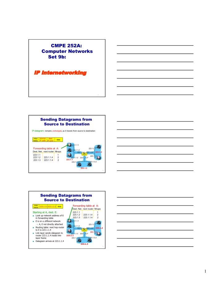
Sending Datagrams from Source to Destination
IP datagram: remains unchanged, as it travels from source to destination
misc fields source IP addr dest IP addr data
- Dest. Net. next router Nhops
223.1.1 1 223.1.2 223.1.1.4 2 223.1.3 223.1.1.4 2
Forwarding table at A:
223.1.1.1 223.1.1.2 223.1.1.3 223.1.2.9 223.1.2.2 223.1.2.1 223.1.3.2 223.1.3.1 223.1.3.27
A B E
223.1.1.4
223.1.1 223.1.3 223.1.2
3
Sending Datagrams from Source to Destination
- Dest. Net. next router Nhops
223.1.1 1 223.1.2 223.1.1.4 2 223.1.3 223.1.1.4 2
Forwarding table at A:
223.1.1.1 223.1.1.2 223.1.1.3 223.1.2.9 223.1.2.2 223.1.2.1 223.1.3.2 223.1.3.1 223.1.3.27
A B E
223.1.1.4
223.1.1 223.1.3 223.1.2
Starting at A, dest. E:
Look up network address of E in forwarding table
E is on a different network
A, E not directly attached
Routing table: next hop router to E is 223.1.1.4
Link layer sends datagram to router 223.1.1.4 inside link- layer frame
Datagram arrives at 223.1.1.4
misc fields 223.1.1.1 223.1.2.2 data