SLIDE 1
Ionic Hubbard chain at half filling
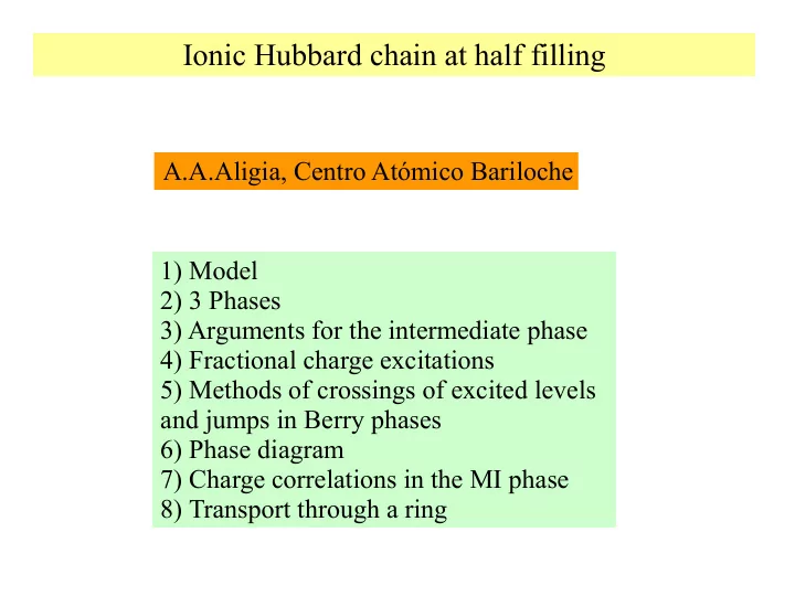
1) Model 2) 3 Phases 3) Arguments for the intermediate phase 4) Fractional charge excitations 5) Methods of crossings of excited levels and jumps in Berry phases 6) Phase diagram 7) Charge correlations in the MI phase 8) Transport through a ring A.A.Aligia, Centro Atómico Bariloche
SLIDE 2 The model: Interest: 1) Neutral-ionic transition in mixed-stack donor-acceptor organic crystals ...DADADA… (Avignon, Balseiro, Proetto, Alascio,
- Phys. Rev. B 33, 205 (1986))
2) Ferroelectric perovskites (Egami et al., Science 261, 1307 (1993), R. Resta and S. Sorella, Phys. Rev. Lett. 74, 4738 (1995), Fabrizio, Gogolin, Nersesyan, ibid 83, 2014 (1999))
SLIDE 3 Phases of the model: Δ
Δ
t<< U - 2Δ MI Mott insulator t<< 2Δ - U BI Band insulator t > 2Δ - U BOW or SDI J = 2t2/(U - 2Δ )+2t2/(U + 2Δ ) J
SLIDE 4
Arguments for the existence of the intermediate SDI phase a) bosonization (Fabrizio et al.) b) Mapping to an SU(3) AF Heisenberg (Batista-Aligia) 1) Electron-hole transformation at sites with energy - Δ 2) Elimination of doubly occupied sites 3) Mapping of the remaining three states into an SU(3) spin Inclusion of nearest-neighbor repulsion V
SLIDE 5
SU(3 ) S=1 |11>
SLIDE 6
Method of crossings of excited levels (weak coupling): For critical systems: Then, crossing of two excited levels denotes a change of phase BI or CDW MI or SDW BOW or SDI S = 1, k = 0, P = -1 S = 0, k = 0, P = 1 S = 0, k = π, P = 1 OPEN SHELL BC
Bi
S = 0, k = π, P = -1 Spin transition Charge transition
SLIDE 7
Method of jumps of Berry phases (strong coupling): 1 2 ... L-1 Charge Berry phase g: phase captured by the ground state in the cycle 0 < Φ < 2π a) In systems with inversion symmetry g = 0 or π (mod. 2π) b) Changes in polarization ΔP = Δ g(e/2π) MI or SDW g = π BI or CDW g = 0
SLIDE 8
Spin Berry phase gs Both methods coincide!! Δ =0, V=1
SLIDE 9
Phase diagram
SLIDE 12
Charge-charge correlation functions in the MI phase r-3ln-3/2r
SLIDE 13
r-3ln-3/2r
SLIDE 14
SLIDE 15
Measuring the charge transition
φ
j L = 4n weak links Mapping to an effective Anderson
SLIDE 16
B>>TK
φ
SLIDE 17
Intensity of the first peak in the transmittance
SLIDE 18
Intensity of the first peak in the transmittance
SLIDE 19
Conductance effective Anderson w~ A R.L.Width w proportional to quasiparticle weigth A G0 = 2e2/h
SLIDE 20
SLIDE 21 Conclusions
The transition from the BI tothe MI takes place through an intermediate dimerized ferroelectric phase The topological jumps allow to determine accurately the transitions Charge correlations in the MI phase have power law decay due to relevant coupling between charge and spin The topological transition can be measured in nanodevices
SLIDE 22 References: Phase diagram: M.E. Torio, A.A. Aligia, and H.A. Ceccatto,
- Phys. Rev. B 64, 121105 (2001) (Rapid Comm)
Dimerized phase: C.B. Batista and A.A. Aligia, Phys. Rev. Lett. 92, 246405 (2004) ; Phys. Rev. B 71, 125110 (2005). Charge dynamics in the MI phase: A.A. Aligia, Phys. Rev. B 69, 041101(R) (2004) (Rapid Comm.) Transport through a ring: A.A. Aligia, K. Hallberg, A.P. Kampf,
- B. Normand, Phys. Rev. Lett. 93, 076801 (2004)
SLIDE 24
SLIDE 25
Opening of a spin gap as U decreases: MI SDI transition
SLIDE 26