investigation of thermal oscillation induced by dryout in
play

Investigation of thermal oscillation induced by dryout in printed - PDF document

Transactions of the Korean Nuclear Society Virtual Spring Meeting July 9-10, 2020 Investigation of thermal oscillation induced by dryout in printed circuit steam generator Jin Su Kwon a , Sung Gil Shin a , Jeong Ik Lee a, *, Sang Ji Kim b a


  1. Transactions of the Korean Nuclear Society Virtual Spring Meeting July 9-10, 2020 Investigation of thermal oscillation induced by dryout in printed circuit steam generator Jin Su Kwon a , Sung Gil Shin a , Jeong Ik Lee a, *, Sang Ji Kim b a Department of Nuclear and Quantum Engineering, Korea Advanced Institute of Science and Technology, 373-1 Guseong-dong Yuseong-gu,Daejeon 305-701, Republic of Korea b Korea Atomic Energy Research Institute 150 Dukjin-dong, Yuseong-gu, Daejon 305-353, Republic of Korea * Corresponding author: jeongiklee@kaist.ac.kr 1. Introduction 
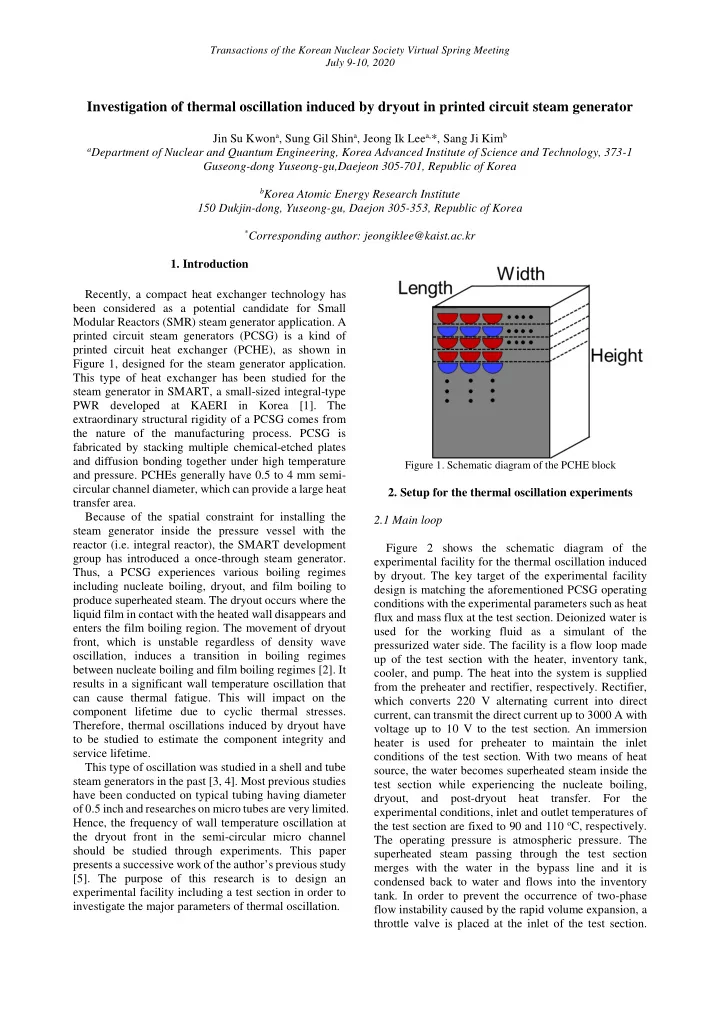
Recently, a compact heat exchanger technology has been considered as a potential candidate for Small Modular Reactors (SMR) steam generator application. A printed circuit steam generators (PCSG) is a kind of printed circuit heat exchanger (PCHE), as shown in Figure 1, designed for the steam generator application. This type of heat exchanger has been studied for the steam generator in SMART, a small-sized integral-type PWR developed at KAERI in Korea [1]. The extraordinary structural rigidity of a PCSG comes from the nature of the manufacturing process. PCSG is fabricated by stacking multiple chemical-etched plates and diffusion bonding together under high temperature Figure 1. Schematic diagram of the PCHE block and pressure. PCHEs generally have 0.5 to 4 mm semi- circular channel diameter, which can provide a large heat 2. Setup for the thermal oscillation experiments transfer area. Because of the spatial constraint for installing the 2.1 Main loop steam generator inside the pressure vessel with the reactor (i.e. integral reactor), the SMART development Figure 2 shows the schematic diagram of the group has introduced a once-through steam generator. experimental facility for the thermal oscillation induced Thus, a PCSG experiences various boiling regimes by dryout. The key target of the experimental facility including nucleate boiling, dryout, and film boiling to design is matching the aforementioned PCSG operating produce superheated steam. The dryout occurs where the conditions with the experimental parameters such as heat liquid film in contact with the heated wall disappears and flux and mass flux at the test section. Deionized water is enters the film boiling region. The movement of dryout used for the working fluid as a simulant of the front, which is unstable regardless of density wave pressurized water side. The facility is a flow loop made oscillation, induces a transition in boiling regimes up of the test section with the heater, inventory tank, between nucleate boiling and film boiling regimes [2]. It cooler, and pump. The heat into the system is supplied results in a significant wall temperature oscillation that from the preheater and rectifier, respectively. Rectifier, can cause thermal fatigue. This will impact on the which converts 220 V alternating current into direct component lifetime due to cyclic thermal stresses. current, can transmit the direct current up to 3000 A with Therefore, thermal oscillations induced by dryout have voltage up to 10 V to the test section. An immersion to be studied to estimate the component integrity and heater is used for preheater to maintain the inlet service lifetime. conditions of the test section. With two means of heat This type of oscillation was studied in a shell and tube source, the water becomes superheated steam inside the steam generators in the past [3, 4]. Most previous studies test section while experiencing the nucleate boiling, have been conducted on typical tubing having diameter dryout, and post-dryout heat transfer. For the of 0.5 inch and researches on micro tubes are very limited. experimental conditions, inlet and outlet temperatures of Hence, the frequency of wall temperature oscillation at the test section are fixed to 90 and 110 o C, respectively. the dryout front in the semi-circular micro channel The operating pressure is atmospheric pressure. The should be studied through experiments. This paper superheated steam passing through the test section presents a successive work of the author’s previous study merges with the water in the bypass line and it is [5]. The purpose of this research is to design an condensed back to water and flows into the inventory experimental facility including a test section in order to tank. In order to prevent the occurrence of two-phase investigate the major parameters of thermal oscillation. flow instability caused by the rapid volume expansion, a throttle valve is placed at the inlet of the test section.

  2. Transactions of the Korean Nuclear Society Virtual Spring Meeting July 9-10, 2020 Moreover, the loop is an open system that is connected the mass flow rate. With the purpose of the visual to air in the inventory tank to eliminate the system observation of dryout instability, the visualization pressure fluctuation. Two bypass lines, which are placed window with quartz having a thickness of 5 mm is at the outlet of the pump and inlet of the test section, are attached to the heating section. After the experiments, the installed to have better controllability of mass flow rate. visual observations of the hydraulic phenomena will be The flow loop is constructed with 0.5 inch tube with used to validate the measurement of thermal oscillation stainless steel 316 except for test section. The working frequency. The resistance heating section and fluid heated in the heater section is cooled by water at visualization window are physically bonded by the room temperature in the cooler. The loop is designed to customized clamp with graphite. The electric resistivity operate at pressure up to 5 bar and temperature up to 130 of graphite is about 8 times higher than that of nichrome o C. so most of the direct current flows into the nichrome section. It indicates that Joule heating mainly occurs at the resistance heating section, not the clamp. The reason why the rubber or Teflon is not used at the connections is due to the wall temperature that can be increased up to 550 o C when dryout occurs in the flow channel. Such a high temperature environment can cause deformation of rubber-like materials so that graphite is chosen as the clamp material. Figure 2. Schematic diagram of the experimental facility 2.2 Test section As shown in Figure 3, the test section consists of three parts: (1) resistance heating section, (2) visualization window and (3) clamp. To facilitate the sophisticated measurement of experimental parameters, the test section has only one semi-circular flow channel in the middle. To produce the superheated steam in the flow channel, the rectifier supplies the DC current to the resistance heating section. The dimension of the heating section is determined by considering the electrical resistivity and structural stability. When the cross- section is wide, electrical resistivity is decreased, and thus, the current is increased under the same electrical potential difference, which leads to a high heat generation by the Joule’s law. On the other hand, the heat Figure 3. Cross section of the test section loss can be larger due to larger heat transfer area and 2.3 Optical fiber fixing between resistance heating section and visualization window becomes difficult. The height is The period of the thermal oscillation induced by fixed to 1 m due to the test section buckling. The semi- dryout can be obtained by measuring the wall circular shaped flow channel and diameter of 2 mm are temperature oscillation near the dryout front. In the derived from the optimized PCSG geometry. One difference in the test section from the typical PCSG flow previous researches, wall temperature was measured using thermocouples by placing them very densely. For channel is that the 0.5 mm capillary stainless steel tube instance, thermocouples are spaced 5 mm apart in the is inserted at the edge of flow channel. It protects the flow direction at the expected dryout occurrence point optical fiber sensor from the boiling of the working fluid [6]. Such a traditional method limits experimental and makes it possible to measure the wall temperature conditions due to a fixed place where dryout occurs. In stably without the interference of nucleated bubbles. The detailed description of optical fiber sensor will be addition, the uncertainty of frequency measurements can be increased with the difficulty in predicting the location discussed in the next section. The graphite seals are of dryout occurrence. In order to resolve the installed symmetrically with respect to the flow channel abovementioned problems, a novel concept of between the heating section and visualization window temperature measurement system is introduced. The since leakage can cause significant measurement error of

Download Presentation
Download Policy: The content available on the website is offered to you 'AS IS' for your personal information and use only. It cannot be commercialized, licensed, or distributed on other websites without prior consent from the author. To download a presentation, simply click this link. If you encounter any difficulties during the download process, it's possible that the publisher has removed the file from their server.

Recommend


More recommend