Investigation of Rack Motion for Seismic Safety Evaluation of a Spent - - PDF document

investigation of rack motion for seismic safety
SMART_READER_LITE
LIVE PREVIEW

Investigation of Rack Motion for Seismic Safety Evaluation of a Spent - - PDF document

Transactions of the Korean Nuclear Society Virtual Spring Meeting July 9-10, 2020 Investigation of Rack Motion for Seismic Safety Evaluation of a Spent Fuel Pool Won Man Park a , Sungman Son a , Dae Kyung Choi a , Kang Hee Lee b , Heung Seok Kang


slide-1
SLIDE 1

Transactions of the Korean Nuclear Society Virtual Spring Meeting July 9-10, 2020

Investigation of Rack Motion for Seismic Safety Evaluation of a Spent Fuel Pool

Won Man Park a, Sungman Son a, Dae Kyung Choi a, Kang Hee Lee b, Heung Seok Kang b, Choengryul Choi a*

aELSOLTEC, Giheung-gu, Yongin, Gyeonggi-do, 16950, Korea bKorea Atomic Energy Research Institute, Yuseong-gu, Daejeon, 34057, Korea *Corresponding author: crchoi@elsoltec.com

  • 1. Introduction

The accurate assessment of the major equipment including the spent fuel storage rack and pool in the nuclear power plant is getting more important and its high resistance against the earthquake is in demand also, with the occurrence of major earthquakes in recent years [1,2]. Spent fuel storage rack is equipment temporarily storing spent fuel assemblies, which are removed from the nuclear reactor before they are moved to the dry cask storage. The rack is not fixed but is free standing on the bottom plane of the pool. The rack can slide on the pool floor as well as tilt in case that a strong motion including the earthquake is applied to the pool. The rack potentially impacts the adjacent racks, pool walls, and/or pool floor. Therefore, investigation of the motion of the rack is very critical in seismic assessment of the spent fuel pool. The free-standing rack is submerged in the coolant. The rack is accelerated, in case of a postulated strong motion such as the earthquake, not only by the motion

  • f the pool because of the earthquake, but also by the

hydrodynamic fluid-structure interaction (FSI) which is induced by the coolant surrounding the rack [2–6]. Adequate assumption and formulation for FSI are very critical for the accurate seismic assessment of the spent fuel storage rack and pool. Hydrodynamic effects of the fluid on the submerged object have been classified into fluid inertia effects, sloshing effect, fluid elasticity effect, and damping effect [6]. The inertia effect of the coolant is considered while the others are generally ignored in seismic assessment of the spent fuel pool [7,8]. However, the rationale of the hypothesis or assumption is not clear. In this study, we investigated the convective effect (or sloshing effect) and impulsive effect (or inertia effect) of the coolant in the spent fuel pool on the storage rack using computational fluid dynamics (CFD)

  • analysis. Then, mechanical behaviors of the racks in the

spent fuel pool were investigated and the rack, which showed the highest acceleration, was predicted using finite element (FE) analysis.

  • 2. Materials and Methods

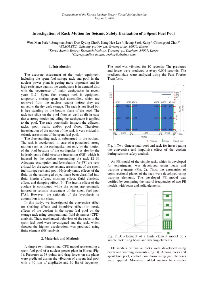
A simple two-dimensional CFD model representing a spent fuel pool of a nuclear power plant in Korea (Fig. 1). Pressures at 38 points and drag forces on six plates were predicted during the vibration of a spent fuel pool with a 40 mm of amplitude and 10 Hz of frequency. The pool was vibrated for 10 seconds. The pressures and forces were predicted at every 0.001 seconds. The predicted data were analyzed using the Fast Fourier Transform.

  • Fig. 1 Two-dimensional pool and rack for investigating

the convective and impulsive effect of the coolant during seismic safety analysis An FE model of the simple rack, which is developed for experiments, was developed using beam and warping elements (Fig. 2). Thus, the geometries of cross-sectional planes of the rack were developed using warping elements. The developed FE model was verified by comparing the natural frequencies of two FE models with beam and solid elements.

  • Fig. 2 Development of a finite element model of a

simple rack using beam and warping elements FE models of twelve racks were developed using beam and warping elements (Fig. 3). Among racks and spent fuel pool, contact conditions using gap elements were applied. Moreover, added masses to consider

slide-2
SLIDE 2

Transactions of the Korean Nuclear Society Virtual Spring Meeting July 9-10, 2020

hydrodynamic effects were calculated using equations introduced in the previously published studies. Seismic evaluation using FE analysis was performed under artificially generated time history ground acceleration data based on the R.G. 1.60 spectrum[9]. The maximum value of ground acceleration was set at 0.3 g.

  • Fig. 3 Finite element models to analyze mechanical

behaviors of racks using solid and beam elements

  • 3. Results

The FFT results of the predicted pressures and drag forces showed that peak amplitude showed at only 10 Hz which is an applied frequency of the vibration (Fig. 4). (a) Pressure (b) Drag force

  • Fig. 4 FFT results of the predicted (a) pressures and (b)

drag forces The natural frequencies of the first three modes of FE models using beam and solid elements were compared. Two models showed similar natural frequencies in 10 % differences (Table 1). Thus, the result showed the development FE model is validated. Table 1 Comparison of the natural frequencies of two FE models

Mode Solid (A) Beam (B) (B)/(A) Shape 1 2030 2232 110% Torsion 2 2837 3012 106% Bending 3 3060 3129 102% Bending

While racks of A1, A2, C1, D1, E1, and G moved with the pool, thus the racks showed the same acceleration with the pool’s acceleration (Fig. 5). Collison between other racks and pool and among the racks were expected. C2 rack showed a higher peak acceleration than others.

  • Fig. 5 Changes in acceleration during vibration of a

spent fuel pool

  • 4. Discussion

Because changes in both pressures and drag forces on the walls of racks and a spent fuel pool showed only

  • ne frequency the same with the frequency of the

applied vibration, we could conclude that only impulsive effect was affected mechanical behaviors of the racks in the spent fuel pool. Therefore, the assumption that only added mass to apply the impulsive effect of the coolant is used for FSI while the convective effect is neglected in the seismic evaluation is proper. Beam elements are generally used for the development of FE models of racks to reduce computational time for FE analysis. The use of mass- beam elements is very common for development. In this study, beam-warping elements were used. In our

  • pinion, it is useful to reduce the time for the

development of the FE model of the racks. A seismic evaluation was performed using FE

  • analysis. While the racks inside moved with the pool,
slide-3
SLIDE 3

Transactions of the Korean Nuclear Society Virtual Spring Meeting July 9-10, 2020

racks beside the wall of the pool showed collision among racks and pool. Gaps between racks and pool walls were greater than those between racks. Thus, racks beside the wall could move more freely and have lesser FSI effects than those located inside.

  • 5. Discussion

The results of this study provide a rationale to support the assumption that only added mass to apply the impulsive effect of the coolant is used for FSI while the convective effect is neglected in the seismic

  • evaluation. Generally, an FE model of a rack with

beam-mass elements is used. However, this study showed that an FE model of a rack with beam-warping elements is also useful. Moreover, the model with beam-warping elements is helpful to reduce the time to develop an FE model of a rack. The results of this study could help to progress the methods for seismic evaluation of a spent fuel pool. Acknowledgement This work was supported by the Korea Institute of Energy Technology Evaluation and Planning (KETEP) and the Ministry of Trade, Industry and Energy (MOTIE)

  • f

the Republic

  • f

Korea (No. 20171510101920). REFERENCES

[1] M. Baba, Fukushima accident: What happened?, Radiat.

  • Meas. Vol. 55, pp. 17–21, 2013.

[2] J. Stabel, M. Ren, Fluid-structure-interaction for the analysis of the dynamics of fuel storage racks in the case of seismic loads, Nucl. Eng. Des. Vol. 206, Issue 2-3, pp. 167– 176, 2011. [3] A. Iwasaki, N. Chigusa, T. Matsuoka, Y. Nekomoto, H. Morita, K. Taniguchi, D. Okuno, Experimental Parameter Study on Free Standing Rack, ASME 2012 Press. Vessel. Pip. Conf., Toronto, 2012. [4] A. Iwasaki, Y. Nekomoto, H. Morita, K. Taniguchi, D. Okuno, T. Matsuoka, N. Chigusa, Analysis Study on Free Standing Rack Under the Earthquake Excitation, ASME 2012

  • Press. Vessel. Pip. Conf., 2012.

[5] R. Lo Frano, Evaluation of the Fluid-Structure Interaction Effects in a Lead-Cooled Fast Reactor, Nucl. Technol. Vol. 189, Issue 1, pp. 1-10, 2015. [6] F. Axisa, J. Antunes, Modelling of Mechanical Systems: Fluid-Structure Interaction, Boston, MA, USA, 2007. [7] H. Ashar, G. DeGrassi, Design and analysis of free- standing spent fuel racks in nuclear power plants: An

  • verview, Int. Conf. Struct. Mech. React. Technol., 1989.

[8] Y. Liu, D. Lu, Y. Wang, H. Liu, The sliding and

  • verturning analysis of spent fuel storage rack based on

dynamic analysis model, Sci. Technol. Nucl. Install., Vol. 2016, Article ID 8368504, 11 pages, 2016. [9] R. 2 Regulatory Guide No. 1.60, Design Response Spectra for Seismic Design of Nuclear Power Plants, 2014.