
SLIDE 1
Inspection Guide for PV Systems—Field Guide
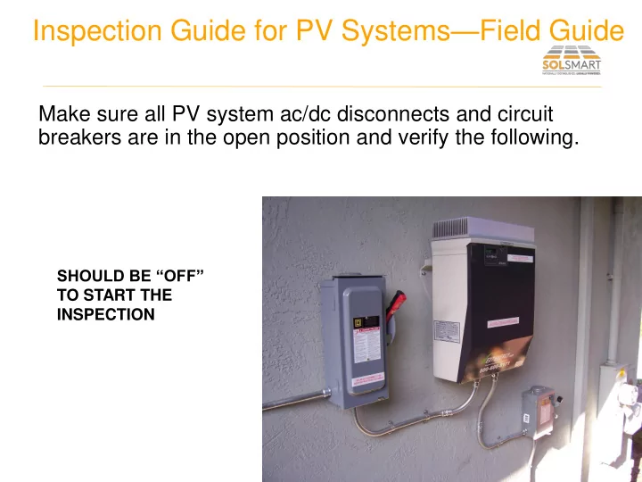
Make sure all PV system ac/dc disconnects and circuit breakers are in the open position and verify the following.
SHOULD BE “OFF” TO START THE INSPECTION
Inspection Guide for PV Systems Field Guide Make sure all PV system - - PowerPoint PPT Presentation
Inspection Guide for PV Systems Field Guide Make sure all PV system ac/dc disconnects and circuit breakers are in the open position and verify the following. SHOULD BE OFF TO START THE INSPECTION 1. All work done in a neat and
SHOULD BE “OFF” TO START THE INSPECTION
NO CONDUCTORS HANGING DOWN ATTRACTING ATTENTION OR DEBRIS
UNSECURED FLEX LAYING ON ROOF RUN ALONG RIDGE CONSISTENT WITH 690.4(F)
Photo courtesy of Bill McGovern