input output
play

Input/Output 1 Range of I/O Hardware Some typical device, - PDF document

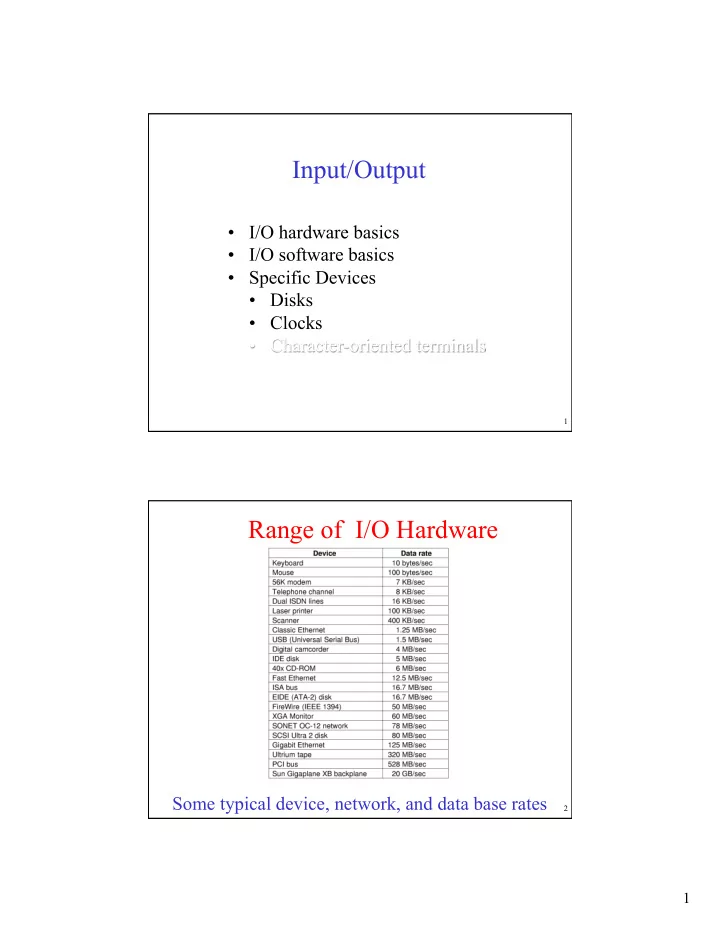
Input/Output 1 Range of I/O Hardware Some typical device, network, and data base rates 2 1 How do we talk to Hardware? Through Device Controllers I/O devices have components: mechanical component electronic component The


  1. Input/Output 1 Range of I/O Hardware Some typical device, network, and data base rates 2 1

  2. How do we talk to Hardware? Through Device Controllers • I/O devices have components: – mechanical component – electronic component • The electronic component is the device controller – may be able to handle multiple devices (e.g., IDE handles two, SCSI handles 8) • Controller's tasks (examples) – interpret instructions from the cpu, translating them into mechanical steps. – convert data between serial bit stream for the hardware and blocks of bytes for the software. – perform error correction as necessary on the data read from the device. – make data available to main memory 3 But how do we talk to the Controller? • Each controller has one or more “ports”. • A port is an “address” that we can read from or write to. • We read from the port (or write to it) by putting the port’s address on the bus. • Every device (including memory) can look at the bus. If you’re a device controller and you see your address on the bus, then you respond to the corresponding command. 4 2

  3. How does a program address a port? • Separate I/O space • Memory-mapped I/O • Hybrid 5 Memory-Mapped I/O Issues (a) A single-bus architecture (b) A dual-bus memory architecture 6 3

  4. Common Layout 7 Programmed I/O To print a string • Loop (bit-spin) checking to see if the device is ready. This requires reading the device’s status port. • Write a character to the output port. • Repeat until all characters have been written. 8 4

  5. Programmed I/O Writing a string to the printer using programmed I/O 9 Interrupts Revisited How interrupts happens. Connections between devices and interrupt controller actually use interrupt lines on the bus rather than dedicated wires 10 5

  6. Interrupt Driven I/O To print a string • When device is ready: – Write a character to the output port. – Go do something else. Probably involving a context switch. • Receive an interrupt because the printer finished printing. • Repeat until all characters have been written. 11 Interrupt-Driven I/O • Writing a string to the printer using interrupt-driven I/O – Code executed when print system call is made – Interrupt service procedure 12 6

  7. Direct Memory Access (DMA) Operation of a DMA transfer 13 I/O Using DMA Printing a string using DMA a) code executed when the print system call is made b) interrupt service procedure 14 7

  8. Principles of I/O Software Issues • Device independence • Naming • Error handling • Synchronous vs. asynchronous transfers • Buffering • Sharable vs. dedicated devices 15 I/O Software Layers Layers of the I/O Software System 16 8

  9. Interrupt Handlers • Steps must be performed in software after interrupt occurs 1. Save regs not already saved by interrupt hardware 2. Set up context for interrupt service procedure 3. Set up stack for interrupt service procedure 4. Ack interrupt controller, reenable interrupts 5. Copy registers from where saved 6. Run service procedure 7. Possible Context Switch. 8. Start running selected process 17 Device Drivers • Logical position of device drivers is shown here • Communications between drivers and device controllers goes over the bus 18 9

  10. Device-Independent I/O Software (1) Uniform interfacing for device drivers Buffering Error reporting Allocating and releasing dedicated devices Providing a device-independent block size Functions of the device-independent I/O software 19 Device-Independent I/O Software (2) (a) Without a standard driver interface (b) With a standard driver interface 20 10

  11. Device-Independent I/O Software (3) (a) Unbuffered input (b) Buffering in user space (c) Buffering in the kernel followed by copying to user space (d) Double buffering in the kernel 21 Device-Independent I/O Software (4) Networking may involve many copies 22 11

  12. User Space I/O Software • Libraries – System calls. • In C, we can have the following function call. count
=
write(fd,
buffer,
nbytes); 
 • The C function “write” is a library function that is linked into the user’s program • It places its arguments on the stack (or in registers) and issues the corresponding trap instruction to request the the necessary kernel code to run – printf is a library function that does a lot of work before issuing a system call: printf(“The
square
of
%3d
is
%6d\n”,
i,
i
*
i);
 • Daemons – “Processes that stay in the background to handle some activity such as email, Web pages, news, printing, etc. are called daemons” – Common example is printer spooling. – Note that some daemons may run purely in kernel mode (such as the page daemon) 23 I/O Software Summary Layers of the I/O system and the main functions of each layer 24 12

  13. Unix I/O Management • I/O devices are made to look like files. – Provides uniform naming – Devices appear as files in the directory /dev • /dev/hda is the first drive on the IDE controller. • /dev/hda4 is partition 4 on the same device. • /dev/lp is the printer – Devices are categorized as either “block” or “character” special files. • Block files support random access to individual blocks, using the seek command. • Character files behave as a stream of characters. Not possible or even meaningful to “seek” on a keyboard. 25 Unix I/O Management • “Special” Files – E.g., /dev/hda – Contains • major and minor device numbers • a flag to indicate whether it is a block special file or a character special file. – Major device number is an index into either • the bdevsw array for block devices, or • the cdevsw array for character devices. • the array entries are structs that hold pointers to functions. – Minor device numbers indicate which instance this is of several equivalent devices. • The minor device number is passed as a parameter to the functions pointed to in the bdevsw and cdevsw arrays. 26 13

  14. UNIX I/O Some of the fields of a typical cdevsw array 27 Disks Disk parameters for the original IBM PC floppy disk and a Western Digital WD 18300 hard disk 28 14

  15. Rotation Time • Inverse of spin rate. Convert minutes to msec as that’s right order of magnitude. • Examples – 4200 rpm • 60,000 msec / 4200 = 100 / 7 = 14 2/7 msec. ≈ 14.3 msec – 5400 rpm • 60,000 msec / 5400 = 100 / 9 = 11 1/9 msec. ≈ 11.1 msec. – 7200 rpm • 60,000 msec / 7200 = 100 / 12 = 8 1/3 msec. ≈ 8.3 msec. – 10K rpm • 60,000 msec / 10,000 = 6 msec. – 15K rpm • 60,000 msec / 15,000 = 4 msec. 29 Disk Formatting A disk sector 30 15

  16. Disk Formatting (3) • No interleaving • Single interleaving • Double interleaving 31 Disk Arm Scheduling • Time required to read or write a disk block determined by 3 factors Seek time – the time needed for the arm to move to 1. the desired cylinder. Rotational delay – the time needed for the desired 2. sector to move under the head. Transfer time – the time needed, after the head is 3. positioned over the the correct sector, for the data to transfer from the device to memory. • Seek time dominates • Error checking is done mostly by controllers 32 16

  17. Computing Access Time • Access Time = seek time + rotational latency + transfer time • Example – Assume 10K rpm, average seek time of 8 msec, 160KB per track. What is the time to access 4KB? • Rotation time = 6 msec. • Rotational latency = ½ rotation time = 3 msec • Transfer time = fraction of track * rotation time = (4 / 160) * 6 msec = 0.15 msec • Access time = 8 + 3 + 0.15 msec = 11.15 msec. 33 Disk Formatting (2) An illustration of cylinder skew 34 17

  18. Calculating Skew • Compute the rotation time (time per rotation) • Compute read time per sector • Divide the track-to-track seek time by the sector read time. • Example – Assume 10K rpm, 300 sectors per track and track-to-track seek time of 800 µsec • Rotation time = 1 minute / 10K rotations = 60,000 msec / 10,000 rev = 6 msec • Sector read time = 6 msec / 300 sectors = 20 µsec per sector • Skew = 800 µsec / 20 µsec = 40 35 Variable Sized Tracks • Physical geometry of a disk with two zones • A possible virtual geometry for this disk 36 18

  19. Disk Arm Scheduling Algorithms • FCFS • Shortest Seek First (SSF) • Elevator – Also known as SCAN • C-SCAN 37 Disk Arm Scheduling Algorithms Pending Initial position requests Shortest Seek First (SSF) disk scheduling algorithm 38 19

  20. Disk Arm Scheduling Algorithms The elevator (aka SCAN) algorithm for scheduling disk requests • Requires a “current direction” 39 Disk Arm Scheduling Algorithms C-SCAN • Like elevator. • But runs express from top down to ground floor. • Provides more “uniform wait time” than SCAN. 40 20

  21. Error Handling • A disk track with a bad sector • Substituting a spare for the bad sector • Shifting all the sectors to bypass the bad one 41 RAID Redundant Array of Inexpensive Disks • Raid level 0 provides parallel access to the data. Strips are multiple sectors in size. • Raid level 1 does the same, but adds backup and improved performance (either copy can be accessed). • Raid level 2 increases the reliability, by using multiple redundancy bits. Here 4 bits of data are encoded with an additional three bits of redundancy to allow for a “Hamming” code. This approach was used effectively on Thinking Machines CM-2 supercomputer. 42 21

Download Presentation
Download Policy: The content available on the website is offered to you 'AS IS' for your personal information and use only. It cannot be commercialized, licensed, or distributed on other websites without prior consent from the author. To download a presentation, simply click this link. If you encounter any difficulties during the download process, it's possible that the publisher has removed the file from their server.

Recommend


More recommend