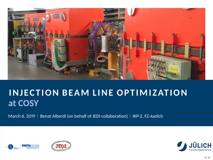

INJECTION BEAM LINE OPTIMIZATION at COSY March 6, 2019 Benat Alberdi (on behalf of JEDI collaboration) IKP-2, FZ-Juelich 0 / 27
Outline COSY facility overview Beam source JULIC Cyclotron Injection Beam Line Injection Optimization IBL optimization Tracking Emittance measurement Next steps 1 / 27
Facility overview 2 / 27
Facility overview
Facility overview p = 0 . 3 − 3 . 7 GeV/c L = 184 m 2 / 27
Facility overview p = 0 . 3 − 3 . 7 GeV/c L = 184 m 3 / 27
Beam source 4 / 27
Beam source 4 / 27
Beam source 2.0-4.5 KeV/A beams. Polarization up to 80%. 5 / 27
JUelich Light Ion Cyclotron (JULIC) 6 / 27
JUelich Light Ion Cyclotron (JULIC) 6 / 27
JUelich Light Ion Cyclotron (JULIC) Originally built for light ions up to Ar, nowadays only H − and D − . 700 tons of iron. f = 20 − 30 MHz . < B > max = 1 . 35 T 6 / 27
JUelich Light Ion Cyclotron (JULIC) Originally built for light ions up to Ar, nowadays only H − and D − . 700 tons of iron. f = 20 − 30 MHz . < B > max = 1 . 35 T Extraction 45 MeV H − or 76 MeV D − beams. 20ms cycles. 6 / 27
Injection Beam Line (IBL) 7 / 27
Injection Beam Line (IBL) 7 / 27
Injection Beam Line (IBL) Provides the connection between JULIC cyclotron and COSY. It is 94m long. 30mm of vertical offset. Composed by 42 quadrupole magnets, 12 dipole magnets and 14 steerer magnets. Diagnostic tools included along the IBL: 8 profile grids and 3 phase probes. Injection dipole at the end. 7 / 27
Injection Dipole 8 / 27
Injection Dipole Injection in COSY is performed by stripping injection into a "distorted orbit". Injection dipole is responsible to align the beam coming from the cyclotron with the beam cycling in COSY. 8 / 27
Injection Dipole Injection in COSY is performed by stripping injection into a "distorted orbit". Injection dipole is responsible to align the beam coming from the cyclotron with the beam cycling in COSY. 8 / 27
Injection 9 / 27
Optimization 10 / 27
Optimization Overview The goal is to make the injection of particles into COSY as efficient as possible. Steps: Develop a model for the IBL. Match design specifications. Control injection point params. Match IBL emittance with COSY acceptance. 10 / 27
Optimization Overview The goal is to make the injection of particles into COSY as efficient as possible. Steps: Develop a model for the IBL. Match design specifications. Control injection point params. Match IBL emittance with COSY acceptance. 10 / 27
Injection optimization IBL 11 / 27
Injection optimization IBL 11 / 27
Injection optimization IBL Not all the quadrupoles are independent → 12 free parameters. Constraints Optimized according to INTERATOM design: Sections 2,4,6: FODO structures. Sections 1, 3+4+5 and 7 achromats. Section 8 controls injection. 11 / 27
Injection optimization IBL and tracking 12 / 27
Injection optimization IBL and tracking 12 / 27
Injection optimization IBL and tracking 12 / 27
Injection optimization IBL and tracking 13 / 27
Injection optimization Tracking at COSY 14 / 27
Injection optimization Tracking at COSY 14 / 27
Injection optimization Tracking at COSY 14 / 27
Combined tracking 15 / 27
Injection optimization Emittance measurement 16 / 27
Injection optimization Emittance measurement 16 / 27
Injection optimization Emittance measurement √ √ � � � 1 � cos( KL ) K sin( KL ) 1 √ D M = √ √ √ · K sin( KL ) cos( KL ) − 0 1 16 / 27
Injection optimization Emittance measurement √ √ � � � 1 � cos( KL ) K sin( KL ) 1 √ D M = √ √ √ · K sin( KL ) cos( KL ) − 0 1 16 / 27
Injection optimization Emittance measurement √ √ � � � 1 � cos( K ′ L ) K ′ sin( K ′ L ) 1 √ D M = √ √ √ · K ′ sin( K ′ L ) cos( K ′ L ) 0 1 − 17 / 27
Injection optimization Emittance measurement Plot of beam size squared vs quadrupole strength for Q17, Y axis. 18 / 27
Outlook The planned upcoming steps for optimizing the injection are: Analyze the injection dipole. Find steerer magnets which allow for independent X and X’ variation of the injected beam in the stripping foil. Combine IBL and COSY in a simulation for a full tracking, including the orbit bump at injection. Match phase space at IBL exit with COSY acceptance. Improve the emittance measurement at IBL. Look for other methods. 19 / 27
Thank you! 20 / 27
References R. Gebel, R. Brings, O. Felden, R. Maier, S. Mey, D. Prasuhn (2013) 20 years of JULIC operation as COSY’s injector cyclotron Proceedings of Cyclotrons 2013, Vancouver, BC, Canada. C. Weidemann (2016) COSY injection and tuning Workshop on Beam Dynamics and Control studies at COSY. A. T. Green, Y. M. Shin (2015) Implementation of quadrupole-scan emittance measurement at Fermilab’s Advanced Supercomputing Test Accelerator (ASTA) 6th International Particle Accelerator Conference. 21 / 27
Spare slides 22 / 27
Spare slides 23 / 27
Spare slides 24 / 27
Spare slides 25 / 27
26 / 27
27 / 27
Recommend
More recommend